Difference between revisions of "ctfDisplay"
(→Execution example) |
(→Execution example) |
||
| (4 intermediate revisions by the same user not shown) | |||
| Line 116: | Line 116: | ||
By setting Max Value and Min Value, you can already see it. | By setting Max Value and Min Value, you can already see it. | ||
| − | 2. | + | 2. As well, set Rmax[/A] range as you want to see. Rmax=0.1 means 1nm, Rmax=0.5 means 2A, and Rmax=1 means 1A. Rmin doesn't usually have to change. |
| − | + | 3. Next, align the noise level. This operation doesn't relate to CTF Correction normally, but it is useful determining CTF. For aligning it, set the parameters Inoise, MTF0 or MTF1. Depending to the media as CCD or Film, you can select either Exponential or Lorentzian about the shape of MTF. MTF0 is Exponential parameter, and MTF1 is Lorentzian parameter. | |
| − | + | 4. Align the signal level. First, Isignal set the same value as Inoise. | |
| − | + | 5. Set CTF parameter. Look at the right bottom of window. | |
| − | + | 5-1:kV: Setting [[Acceleration voltage]][kV] | |
| − | + | 5-2: Cs/Cc: Setting [[Spherical aberration coefficient]] [[Cs]][mm], Chromatic aberration coefficient [[Cc]][mm] | |
| − | + | 5-3: Ai: Setting [[Illumination Aperture]] Ai[mrad] (e.g. LaB6: about 0.15-0.45(in Normal Field), 0.03-0.05(in Thermal Field), 0.02-0.04(in Cold Field): The value is different according to situation.) | |
| − | + | Speaking about this value, Fitting can explain the signal finally. Even if you use same Electron gun, the value might be different according to situations. It is one of important parameter for considering the projection environment. | |
| − | + | 5-4: nDivision: Setting number of division: It usually needs not to change. If SN is not good, try to lower this value. | |
| − | + | 6. Determine Defocus. | |
| − | + | 6-1: If Thon Ring is the ellipsoid, set AxisFor0 Angle as the longer and shorter axis are 0-axis or 1-axis. Both axis is fine. When these axis fit better, you can see the Irregularities of signal(blue line) more clearly. | |
| − | + | 6-2: Change each value of defocus0/defocus1 as fitting the dent(Thon Ring) to valley of CTF(red line). Vertical line means Thon Ring. | |
| − | + | 6-3: When Isignal/Ai/defocus fit better, it can explain the shape on 1st Thon Ring. | |
| − | + | The following is the example of good setting on the whole. | |
| − | [[ | + | [[File:ctfDisplay-example.png|center|840px]] |
| − | + | 7. Save with pushing Save button. | |
| − | + | 8. Exit with closing the window, or pushing q key, or pushing saveAndExit button or Exit button. | |
Latest revision as of 08:06, 25 August 2014
ctfDisplay is one of Integration Tools(Integration Commands) for setting CTF Parameters (e.g. Defocus). There is the command that determines CTF Parameters automatically. But, In the case of low contrast or low SN-Ratio(e.g. using cryo-EM data), or checking automatically determined data as defocus, use it.
List of option
Main option
| Option | Essential/Optional | Description | Default |
|---|---|---|---|
| -i | Optional | Input: mrcImage(FFT) | NULL |
| -o | Optional | Input and Output: ASCII(CTF Information) | stdout |
| -Rmax | Optional | Rmax: [A-1] | 0.2 |
| -Imax | Optional | Intensity max | 0.2 |
| -Imin | Optional | Intensity min | 0.2 |
| -AutoRange | Optional | ||
| -Log | Optional | Log of Intensity | |
| -c | Optional | ConfigurationFile | NULL |
| -m | Optional | Mode | 0 |
| -h | Optional | Help |
-m details
| Value | Description |
|---|---|
| 0 |
Execution example
Here, Here, determine CTF Parameters by using provided data and ctfDisplay. First, execute most simple way. Beforehand, get Media:example.fft by Fourier Transformation of Media:example.mrc by mrcImageFFT.
Then, determinate Parameters(e.g. Defocus) by using ctfDisplay.
$ mrcImageFFT -i example.mrc -o example.fft
$ ctfDisplay -i example.fft -o example.ctfinfo
Determined CTF Parameters are stored in example.ctfinfo file. Next, perform CTF Correction by using this file.
The following shows how to use the ctfDisplay. Download the data at here.
$ ctfDisplay -i example.fft -o example.ctfinfo
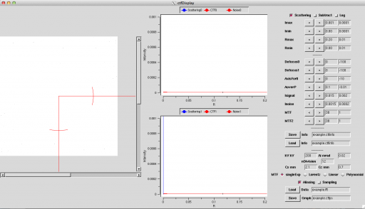
It can execute by the above command. If .ctfinfo file is exist, its data is read. Otherwise, it is set automatically. And, the following window opens.
The left side of window displays the spectrum of Fourier Transformation, the middle side displays the spectrum's average by angle, and the right side shows each parameter for CTF.
Calculate CTF Function by the following method.
1. Align Imin/Imax so that the spectrum can be seen. Pushing Log button may be easy to see. If you can't see it, set Imin=0.00001, Imax=100000 and push Log button. Then, there is blue spectrum on somewhere. After that, set range of this spectrum with looking carefully. If you know the range beforehand, at executing
$ ctfDisplay -i example.fft -o example.ctfinfo -Imin 0.01 -Imax 100 -Log
By setting Max Value and Min Value, you can already see it.
2. As well, set Rmax[/A] range as you want to see. Rmax=0.1 means 1nm, Rmax=0.5 means 2A, and Rmax=1 means 1A. Rmin doesn't usually have to change.
3. Next, align the noise level. This operation doesn't relate to CTF Correction normally, but it is useful determining CTF. For aligning it, set the parameters Inoise, MTF0 or MTF1. Depending to the media as CCD or Film, you can select either Exponential or Lorentzian about the shape of MTF. MTF0 is Exponential parameter, and MTF1 is Lorentzian parameter.
4. Align the signal level. First, Isignal set the same value as Inoise.
5. Set CTF parameter. Look at the right bottom of window.
5-1:kV: Setting Acceleration voltage[kV]
5-2: Cs/Cc: Setting Spherical aberration coefficient Cs[mm], Chromatic aberration coefficient Cc[mm]
5-3: Ai: Setting Illumination Aperture Ai[mrad] (e.g. LaB6: about 0.15-0.45(in Normal Field), 0.03-0.05(in Thermal Field), 0.02-0.04(in Cold Field): The value is different according to situation.)
Speaking about this value, Fitting can explain the signal finally. Even if you use same Electron gun, the value might be different according to situations. It is one of important parameter for considering the projection environment.
5-4: nDivision: Setting number of division: It usually needs not to change. If SN is not good, try to lower this value.
6. Determine Defocus.
6-1: If Thon Ring is the ellipsoid, set AxisFor0 Angle as the longer and shorter axis are 0-axis or 1-axis. Both axis is fine. When these axis fit better, you can see the Irregularities of signal(blue line) more clearly.
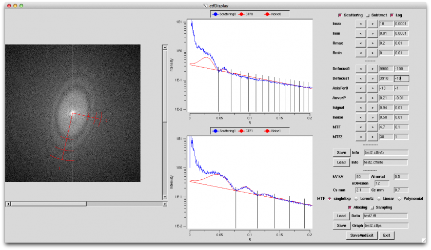
6-2: Change each value of defocus0/defocus1 as fitting the dent(Thon Ring) to valley of CTF(red line). Vertical line means Thon Ring.
6-3: When Isignal/Ai/defocus fit better, it can explain the shape on 1st Thon Ring.
The following is the example of good setting on the whole.
7. Save with pushing Save button.
8. Exit with closing the window, or pushing q key, or pushing saveAndExit button or Exit button.

