「mrc3Dto2D」の版間の差分
| (同じ利用者による、間の1版が非表示) | |||
| 行148: | 行148: | ||
</tr> | </tr> | ||
</table> | </table> | ||
| + | <br> | ||
===オプション必須項目のみの場合=== | ===オプション必須項目のみの場合=== | ||
| 行167: | 行168: | ||
</tr> | </tr> | ||
</table> | </table> | ||
| − | + | <br> | |
| + | |||
===オプション -Rot1 -Rot2 -Rot3=== | ===オプション -Rot1 -Rot2 -Rot3=== | ||
| 行186: | 行188: | ||
標準誤差<br> | 標準誤差<br> | ||
</td> | </td> | ||
| − | <td | + | <td>0<br> |
0.175<br> | 0.175<br> | ||
0.00302838<br> | 0.00302838<br> | ||
| 行194: | 行196: | ||
</tr> | </tr> | ||
</table> | </table> | ||
| + | <br> | ||
===オプション -EulerMode=== | ===オプション -EulerMode=== | ||
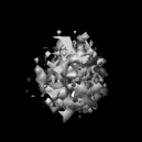
| 行221: | 行224: | ||
</tr> | </tr> | ||
</table> | </table> | ||
| − | + | <br> | |
| + | |||
| + | <div>以降はすべてRot 0 180 30で設定</div> | ||
| + | |||
===オプション -InterpolationMode=== | ===オプション -InterpolationMode=== | ||
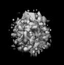
====InterpolationMode:0==== | ====InterpolationMode:0==== | ||
| 行241: | 行247: | ||
</tr> | </tr> | ||
</table> | </table> | ||
| + | <br> | ||
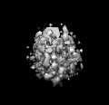
| − | + | ====InterpolationMode:1==== | |
<table> | <table> | ||
<tr> | <tr> | ||
| 行260: | 行267: | ||
</tr> | </tr> | ||
</table> | </table> | ||
| + | <div>デフォルトは1なので画像に変化はない。</div> | ||
| + | <br> | ||
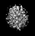
====InterpolationMode:2==== | ====InterpolationMode:2==== | ||
| 行279: | 行288: | ||
</tr> | </tr> | ||
</table> | </table> | ||
| + | <br> | ||
====InterpolationMode:3==== | ====InterpolationMode:3==== | ||
2014年1月20日 (月) 00:32時点における最新版
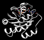
mrc3Dto2Dとは3D画像から2D画像を生成するEosのコマンドである。ここでいう3D画像と2D画像とは、それぞれ主に参照像、投影像のことを指す。類似構造や結晶構造(PDBファイル)から様々な角度の投影像を取得できる。得られた投影像は、単粒子解析において粒子の角度決定に用いられる。
オプション一覧
メインオプション
| オプション | 必須項目/選択項目 | 説明 | デフォルト |
|---|---|---|---|
| -i | 必須 | 入力ファイル設定 | NULL |
| -o | 必須 | 出力ファイル設定 | NULL |
| -Rot1 | 選択 | 最初の回転 | 0.0 360.0 10 |
| -Rot2 | 選択 | 2度目の回転 | 0.0 360.0 10 |
| -Rot3 | 選択 | 最後の回転 | 0.0 360.0 10 |
| -EulerMode | 選択 | オイラー角の回転モード設定 | ZOYS |
| -InterpolationMode | 選択 | 展開モード | 1 |
| -AreaMode | 選択 | エリアモード:投影をする全空間の形 0:立方体 1:球 |
0 |
| -m | 選択 | モード | 0 |
| -h | 選択 | ヘルプを表示 |
モードの詳細
| モード | 説明 |
|---|---|
| 0 | 投影像の数はそのまま |
| 1 | 回転角を減少させる nRot3=1とRot2の軸が2D画像平面に垂直であるなら、投影像の数を減少させることができる |
-InterpolationModeの詳細
| モード | 説明 |
|---|---|
| 0 | 最短距離法 |
| 1 | 線形補間法 |
| 2 | 3次補間法 |
| 3 | 多項式法 |
オプション-EAのRotModeの設定の詳細
一桁目:	どの軸から回転を始めるか設定
二桁目:	回転軸の順番を設定1
O…Z→Y→Xの順に回転軸を変更する
E…Z→X→Yの順に回転軸を変更する
三桁目:	回転軸の順番の設定2
Y…順番を維持する
N…順番を逆順にする
四桁目:	回転方法を設定
S…物体そのものをまわす
R…座標を移動させる
実行例
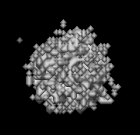
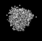
入力画像
pdbInfoでみた入力ファイルの詳細
| XY平面 | YZ平面 |
 |
 |
オプション必須項目のみの場合
 |
最小 最大 |
0 0.186008 |
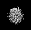
オプション -Rot1 -Rot2 -Rot3
| XY平面 | YZ平面 | ||
 |
 |
最小 最大 |
0 0.175 |
オプション -EulerMode
| XY平面 | YZ平面 | ||
 |
 |
最小 最大 |
0 0.175 |
オプション -InterpolationMode
InterpolationMode:0
 |
最小 最大 |
0 0.2125 |
InterpolationMode:1
 |
最小 最大 |
0 0.175 |
InterpolationMode:2
 |
最小 最大 |
-0.0325619 0.213961 |
InterpolationMode:3
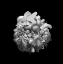 |
最小 最大 |
-5.4667 184.383 |
