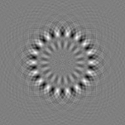
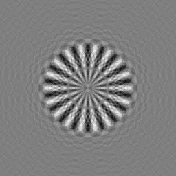
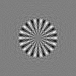
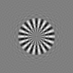
CTF Correction
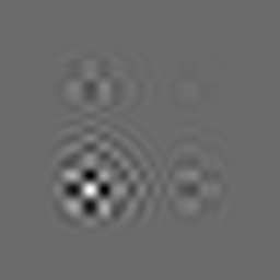
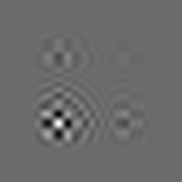
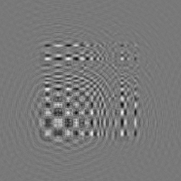
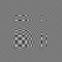
TEM images are generally shot as demodulated according to the shooting condition. If trying to interpret the shot images as they are, a problem will occur. In particular, for biological samples which have low contrast, TEM tries to increase contrast by increasing the defocusing quantity. Consequently, the image is demodulated greatly.
Thinking in a real space, the image observed is an image where PSF (Point Spread Function), which shows how each point on the real image expands, is convoluted for each point.
On the other hand, in an inverse space (Fourier space), the image observed is Fourier-transformed by calculating production between the true image and CTF (Contrast Transfer Function), which is generated by applying the Fourier transformation to PSF (Point Spread Function).
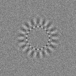
This section summarizes contrast compensation methods as calculating the influence of CTF using Eos commands and understanding the meaning of TEM images.
The following are CTF documents. You can refer to those.
http://www.yasunaga-lab.bio.kyutech.ac.jp/EosJ/images/e/e5/ElectronMicrographAnalysis1.pdf
http://www.yasunaga-lab.bio.kyutech.ac.jp/EosJ/images/8/86/ElectronMicrographAnalysis2.pdf
Contents
- 1 To obtain images demodulated by CTF
- 2 Determination of CTF parameters
- 3 To compensate demodulation by CTF
- 4 Integrated process definition document regarding CTF-compensation
- 4.1 Example 1 CTF-compensation using Makefile
- 4.2 Example 2 CTF correction using Makefile-2
- 4.3 Example 3 CTF effects on the Siemens star
- 4.4 Example 4 CTF influence on images with noises
- 4.5 NS ratio influence =
- 4.6 Example 5 defocus influence on images
- 4.7 Example 6 Averaging of images with different amounts of defocus
- 4.8 Example 7 Averaging of images with different amount of defocus 2
- 5 Others
To obtain images demodulated by CTF
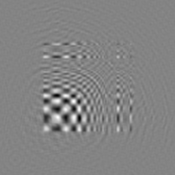
Eos has several tools to simulate how a true image is demodulated. A tool to observe the influence of CTF on the image is mrcImageCTFObservation. Let’s demodulate an image using this program. Let’s demodulate an image using this program. Let’s download example-002.mrc example-002.mrc and use it.
$ mrcImageCTFObservation -i example-002.mrc -o example-002.prectf -kV 200 -Cs 1.2 -df 30000 -A 0.1 -Ain 0.3 -ctfMode 33
$ Display2 -i example-002.mrc & $ Display2 -i example-002.mrc -Inverse &
In addition, to observe the CTF function itself interactively, a tool named ctfDisplay is usable. This tool is also used interactively to determine the CTF function itself.
$ mrcImageFFT -i example-000.mrc -o example-000.fft
$ ctfDisplay -i example-000.fft -o example-000.ctfinfo
Determination of CTF parameters
Eos has a program, ctfDetermine, which determines CTF parameters (defocusing quantity) automatically. These parameters can be determined if the SN ratio is sufficiently high and an area called a tone ring in which contrast is zero appears clearly. This program does not support astigmatism currently.
So, use the ctfDisplay command if data such as cryo-EM show small contrast, if the SN ratio is not enough, or to confirm the automatically determined defocusing quantity.
In this section, let’s use ctfDisplay to determine CTF parameters using the supplied data.
First, let’s execute the simplest method. Use mrcImageFFT to Fourier-transform the image initially. Then, use ctfDisplay to determine the defocusing quantity.
$ mrcImageFFT -i example.mrc -o example.fft
$ ctfDisplay -i example.fft -o example.ctfinfo
The determined CTF parameters are saved in a file named example.ctfinfo. Then, CTF is to be compensated using this file.
Hereinafter this section describes easy usage of the ctfDisplay command. Download the data from (Media:example.mrc, Media:example.fft).
$ ctfDisplay -i example.fft -o example.ctfinfo
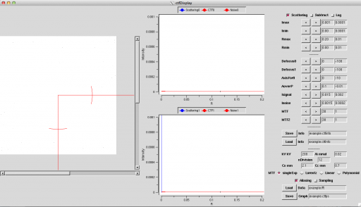
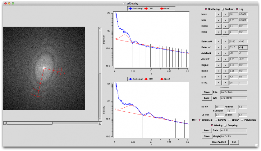
By specifying the command line like above, this command can be executed. File .ctfinfo is set up automatically even if not specified, and data of the file are read in if the file exists. As a result, the following window is opened.
In this window, the left-hand pane shows the Fourier-transformed spectrum, the middle panes display the graphs generated by averaging that spectrum in the angle direction, and the right-hand area displays various parameters for CTF.
Quote CTF using the procedure below:
1. Adjust Imin or Imax so that a spectrum appears. The spectrum can be detected more easily when the Log button is pressed. If you are not sure, set Imin=0.00001 and Imax=100000, and press the Log button. A blue spectrum will appear somewhere. After that, set up the parameters as looking at the range of that spectrum well. If you know parameter values initially, you can set them up from scratch by specifying like below during start-up:
$ ctfDisplay -i example-000.fft -o example-000.ctfinfo -Imin 0.01 -Imax 100 -Log
Operation movie: [(.mov)] [(.mp4)]
2. Set up Rmax[/A] in the same way in the range you wish to view. Rmax=0.1, Rmax=0.5, and Rmax=1 mean 1nm, 2A, and 1A, respectively. Rmin does not need to be changed so much.
operation movie: [(.mov)] [(.mp4)
3. Then, adjust noise level. Although this operation is not related to CTF compensation itself generally, it is useful when determining CTF. The parameters to adjust noise level are Inoise, MTF0, or MTF1. Either the exponential function type or the Lorentz type can be selected as a MTF type according to the medium such as CCD or film. MTF0 is the parameter of the exponential function type, and MTF1 is the parameter of the Lorentz type.
※ Note: Inoise and Isignal are different from the displayed values of I (including Imin, Imax; those are powers and are square of intensities. A possible confusion comes from using the same symbol I. Taking the square root may help adjusting.
※ MTF can be different depending on axes. Main cause is a drift. The current version does not deal with multiple MTFs.
4. Adjust signal level. First, set the same value as applied to Inoise on Isignal.
operation movie(3, 4): [(.mov)] [(.mp4)]
5. Set up the CTF parameters.
5-1: Set up acceleration voltage [kV].
5-2: Set up spherical aberration coefficient Cs[mm] and chromatic aberration coefficient Cc[mm].
5-3: Set up Ai[mrad], which is the irradiation half angle. (The standard values are around 0.15-0.45 for LaB6, around 0.03-0.05 in the thermal field, and around 0.02-0.04 in the cold field. They are different according to the condition.)
Ai values vary largely depending on the illumination conditions. It is the important parameter to determine the shot conditions.
5-4: Set up a division number. This parameter does not need to be changed generally. Lower this value if the SN ratio is low at any cost.
6. Determine defocusing.
6-1 If the tone ring is an ellipse, set up the angle of AxisFor0 so that the long and short axes of the ellipse align with axes 0 and 1, respectively. It is no problem whichever of the long and short axes aligns with axis 0. When those axes are aligned with each other successfully, the concavity and convexity of the signal (blue line) become clear most.
6-2 Adjust defocusing by changing the defocus 0 or defocus 1 parameter, respectively so that the trough of CTF (red line) comes to the dent (tone ring).
6-3 The shape of the first tone ring can be explained well by adjusting Isignal, Ai, or defocus parameter skillfully.
When all are set up well, you will see this on screen.
7. Press the Save button to save the parameters.(output CTF info. file)
8. To exit, close the window, press the q key, press the saveAndExit button, or press the Exit button.
operation movie:(5 ~ 8): [(.mov)] [(.mp4)]
To compensate demodulation by CTF
On Eos, the mrcImageCTFCompensation or mrcImageMultiCTFCompensation command is used to compensate demodulation by CTF. The former is used to compensate the CTF demodulation of a piece of image, and the latter is used to compensate that of two or more pieces of images with the same field of view (defocusing series).
The mrcImageCTFCompensation command compensates CTF based on the information on CTF output by ctfDisplay. By specifying like below,
$ mrcImageCTFCompensation -i example.fft -o example.ctf -info2 example.ctfinfo -m 1
only phase can be compensated in the CTF parameters.
To use mrcImageMultiCTFCompensation, alignment must be performed in advance among the images overlaid with each other. To increase the precision of alignment, it is preferable to use the respective images after their phases are compensated.
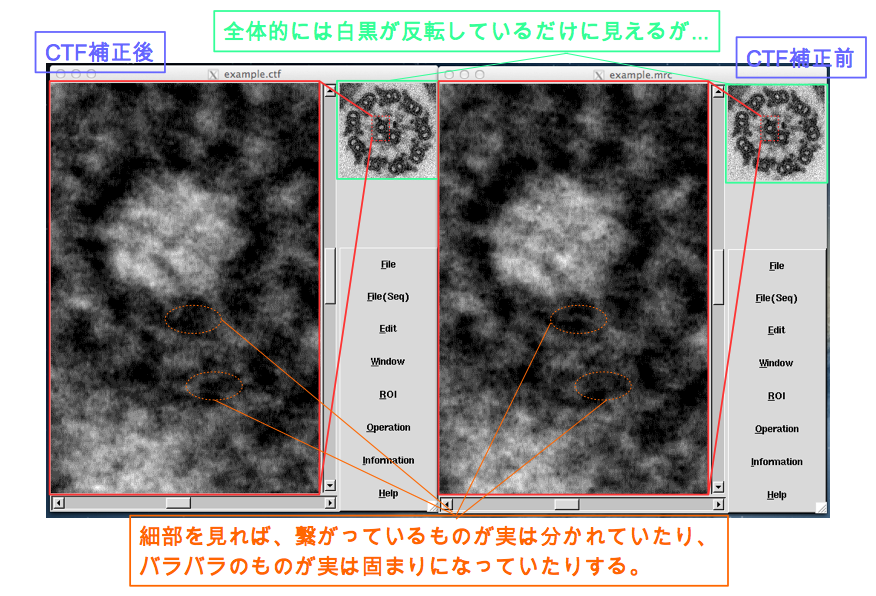
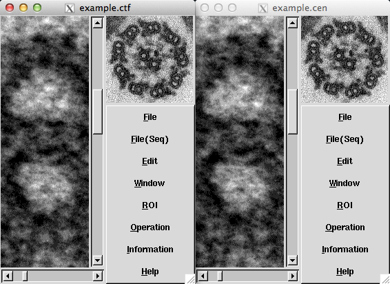
The example of this tutorial (example.mrc) shows cross-sectional images of a chlamydomonas flagellum demodulated by CTF. The entire picture is just an image on which black and white are inverted. However, you will find that the shape and position has become greatly different by observing the images, especially the shapes of protein molecules (outer arm dynein).
Let’s observe the images by Display2.
$ Display2 -i example.ctf -Inverse & $ Display2 -i example.mrc &
By comparing the original and compensated images, you will recognize that the entire structure has not been changed so much, but the structure in the order of nanometer has become greatly different. In short, compensation of CTF demodulation (hereinafter simply called CTF-compensation) is not needed particularly to observe the structure of an entire cell, however, such compensation is indispensable to argue minute structures of the protein level.
Integrated process definition document regarding CTF-compensation
Below are examples of CTF-compensation which includes automatic pre-processing using MakefileYou can refer to Integration commands supplied by Eos#Integration commands supplied by Eos which summarizes Makefile
Example 1 CTF-compensation using Makefile
Images are generally pre-processed a bit more. Hereafter this section describes an example of Makefile used for very general CTF-compensation. When typing like below,
$ make
a help file to execute making is displayed. By typing like below,
$ make TIF2CTF
all the files with the .tif suffix in the executed directory are CTF-compensated. This is not a full-automatic definition document because there are steps to determine and confirm CTF interactively using ctfDisplay on the way.
The file content
.SUFFIXES: .tif .mrc .cen .nor .fft .ctfinfoauto \
           .ctfinfo .ctf .ctfps

-include TIFS
-include MRCS
-include CENS
-include NORS
-include FFTS
-include CTFAutoList
-include CTFInfoList
-include CTFS

#
# Setting Parameter
# [A/pixel]
RESOLUTION=3.80

# JOB Number
JN=-j 4

#####################
Help::
	@echo "----- How To Use -----"
	@echo "1. Prepare files(xxxx.tif) to be analyzed."
	@echo "2. make TIF2CTF"
	@echo ""
	@echo "--- Special Target ---"
	@echo "make DispCEN"
	@echo "make DispCTF"
	@echo "make PrintCTF"
	@echo ""
	@echo "--- Current Parameter ---"
	@echo "RESOLUTION: $(RESOLUTION) [A/pixel]"
	@echo "Job number for make: $(JN)"

mrc:          $(TIFS:.tif=.mrc)
cen:          $(MRCS:.mrc=.cen)
nor:          $(CENS:.cen=.nor)
fft:          $(NORS:.nor=.fft)
ctfinfoauto:  $(FFTS:.fft=.ctfinfoauto)
ctfinfo:      $(CTFAutoList:.ctfinfoauto=.ctfinfo)
ctf:          $(CTFInfoList:.ctfinfo=.ctf)
ctfps:        $(CTFInfoList:.ctfinfo=.ctfps)

TIF2CTF::
	make TIFS; make $(JN) mrc;
	make MRCS; make $(JN) cen;
	make CENS; make $(JN) nor;
	make NORS; make $(JN) fft;
	make FFTS; make $(JN) ctfinfoauto;
	make CTFAutoList; make ctfinfo;
	make CTFInfoList; make $(JN) ctf;
	make CTFS

TIFS::
	echo "TIFS=\\" > TIFS
	ls -1 *.tif | sed s/tif/tif\\\\/ >> TIFS
	echo "" >> TIFS

MRCS::
	echo "MRCS=\\" > MRCS
	ls -1 *.mrc | sed s/mrc/mrc\\\\/ >> MRCS
	echo "" >> MRCS

CENS::
	echo "CENS=\\" > CENS
	ls -1 *.cen | sed s/cen/cen\\\\/ >> CENS
	echo "" >> CENS

NORS::
	echo "NORS=\\" > NORS
	ls -1 *.nor | sed s/nor/nor\\\\/ >> NORS
	echo "" >> NORS

FFTS::
	echo "FFTS=\\" > FFTS
	ls -1 *.fft | sed s/fft/fft\\\\/ >> FFTS
	echo "" >> FFTS

CTFAutoList::
	echo "CTFAutoList=\\" > CTFAutoList
	ls -1 *.ctfinfoauto | sed s/ctfinfoauto/ctfinfoauto\\\\/ >> CTFAutoList
	echo "" >> CTFAutoList

CTFInfoList::
	echo "CTFInfoList=\\" > CTFInfoList
	ls -1 *.ctfinfo | sed s/ctfinfo/ctfinfo\\\\/ >> CTFInfoList
	echo "" >> CTFInfoList

CTFS::
	echo "CTFS=\\" > CTFS
	ls -1 *.ctf | sed s/ctf/ctf\\\\/ >> CTFS
	echo "" >> CTFS

.tif.mrc:
	tiff2mrc -i $*.tif -o $*.mrc -r $(RESOLUTION) -m 0

.mrc.cen:
	mrcImageCenterGet -i $*.mrc -o $*.cen -Nx 1000 -Ny 1000

DispCEN:
	for i in $(CENS) ;\
	do \
		echo $$i;\
		Display2 -i $$i;\
	done

.cen.nor:
	mrcImageAbnormalValueRemove -i $*.cen -o $*.nor -u 65535 16384 -m 1

.nor.fft:
	mrcImageFFT -i $*.nor -o $*.fft

.fft.ctfinfoauto:
	ctfDetermine -i $*.fft -o $*.ctfinfoauto -D 50000 -m 128 \
				 -CutLow 0.025 -CutHigh 0.15 -d 3 -Cc 0.7 -Cs 2.1

.ctfinfoauto.ctfinfo:
	if [ ! -f $*.ctfinfo ] ; then \
		if [ -f default.ctfinfo ] ; then \
	 		cat default.ctfinfo >> $*.ctfinfo ; \
		else \
	 		cat $*.ctfinfoauto >> $*.ctfinfo ; \
		fi \
	fi
	ctfDisplay -i $*.fft
	mv $@ $@.tmp
	grep .: $@.tmp > $@
	awk '!/.ctfinfo/ {print $$0}' $@ > default.ctfinfo

.ctfinfo.ctf:
	mv $*.ctfinfo $*.ctfinfo.tmp2
	grep .: $*.ctfinfo.tmp2 > $*.ctfinfo
	mrcImageCTFCompensation -i $*.fft -info2 $*.ctfinfo -o $*.ctf -m 1

.ctf.ctfps:
	mrcImagePrint -i $*.ctf -o $*.ctfps  -I -A  -m 17 -S 0.08

DispCTF:
	for i in $(CTFS) ;\
	do \
		echo $$i;\
		Display2 -i $$i -Inverse;\
	done

PrintCTF:
	for i in $(CTFS) ;\
	do \
		echo $$i;\
		if [ -f $$i ] ; then \
			make `basename $$i .ctf`.ctfps; \
		fi \
	done
Example
make TIF2CTF
make DispCEN &
make DispCTF &
Example 2 CTF correction using Makefile-2
An example is given using another image.
File contents
this Makefile is used. You do this in CTFCorrection/CTFCorrection directory.
Run example
make all2
Run results
|
original_image_file |
before_CTF_correction |
after_CTF_correction |
When the defocus amount gets less, image details will get closer to reality leading to an easy interpretation of the image. In this example, you can recognize three whitish points in the protein part in the original image. This feature is not apparent before the CTF correction (smeared in grey), but after the correction it gets apparent. The other feature, a black hole at the center of the original image, went whitish before the correction, but gets appreciable after the correction.
Example 3 CTF effects on the Siemens star
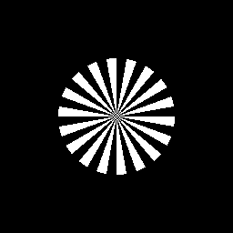
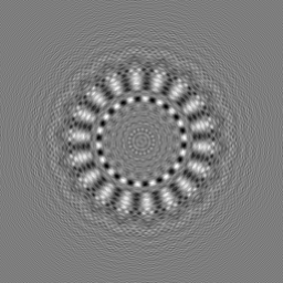
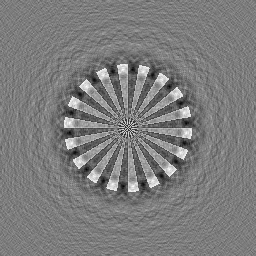
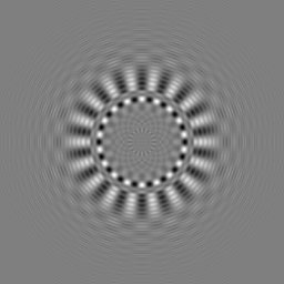
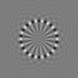
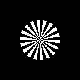
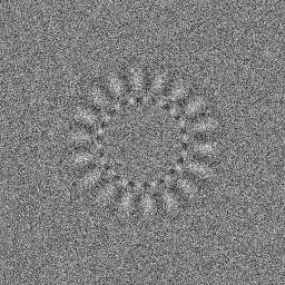
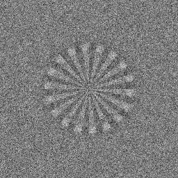
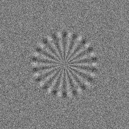
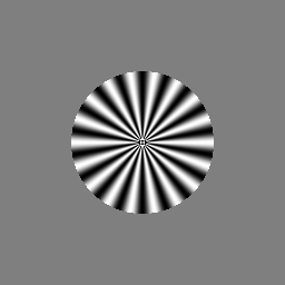
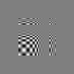
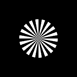
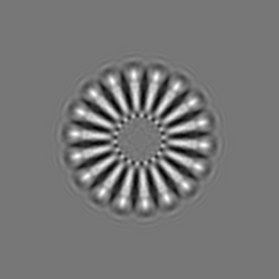
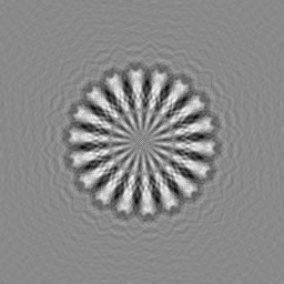
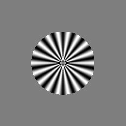
When a Siemens star images is used, improvements on resolution are quite recognizable because CTF corrections make large differences in the images. The Siemens star image is made by mrcImageSiemensStar
Run example
The following commands, which use the Makefile in example 2, are for comparison between "before" and "after" CTF correction of the Siemens star image.
make all2S
SiemensStar (step)
|
original_image |
before_CTF_correction(contrast reversal) |
after_CTF_correction( information_on_CTF_correction) |
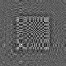
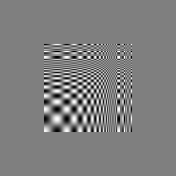
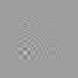
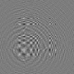
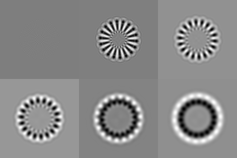
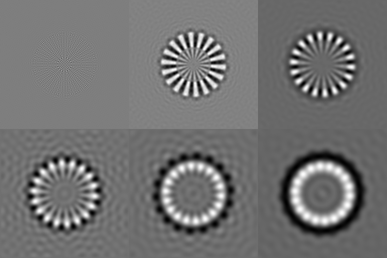
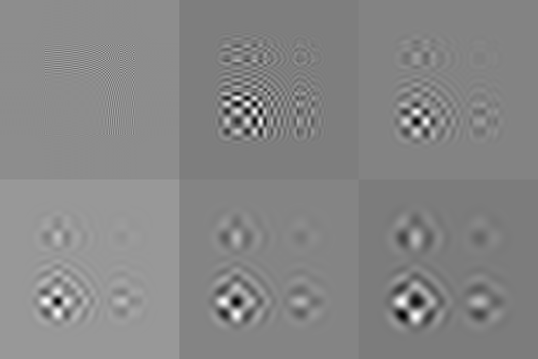
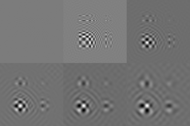
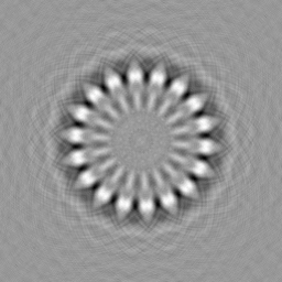
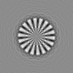
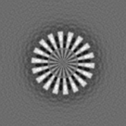
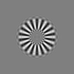
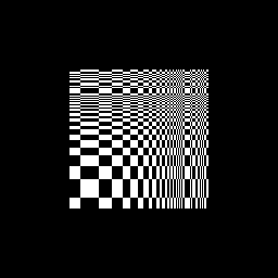
Before the CTF correction, the image has a grey ring (r=44 pix). The inner and outer zones of the ring have different black and white patterns (the inner is reversed). After correction, black and white patterns are restored with a grey ring at r=12 pix。As the Length of the images are 1.72[Å/Pixel], the resolution improved 26Å → 7Å.It is to be noted that, as you notice black and white patterns around 26Å or inside 7Å, high frequency components are restored, because the original image is not like a sine wave but has a step-like feature.。
As shown below, by changing an option (mrcImageSiemensStar(-Shape)), you can observe the changes due to CTF correction of he Siemens star with Cos-type or with a linear feature.
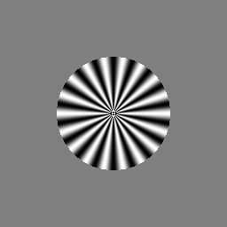
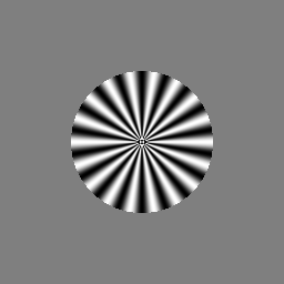
Siemens Star (Cos)
Changes
### For mrcImageSiemensStar
#SSTAR_SHAPE=0
SSTAR_SHAPE=1
Run with similar commands
|
original_image |
Before_CTF_correction(reversed contrast) |
After_CTF_correction(information_on_CTF_correction) |
In the images with a sine wave feature (images in the real world), the grey ring and the inner black and white patterns, observed before CTF correction, are not restored.
Linear (step)
Changes
### For mrcImageSiemensStar
#SSTAR_SHAPE=0
SSTAR_SHAPE=2
Run with similar commands
|
original_image |
Before_CTF_correction(reversed contrast) |
After_CTF_correction(information_on_CTF_correction) |
Linear(Cos)
Changes
### For mrcImageSiemensStar
#SSTAR_SHAPE=0
SSTAR_SHAPE=3
Run with similar commands
|
original_image |
Before_CTF_correction(reversed contrast) |
After_CTF_correction(information_on_CTF_correction) |
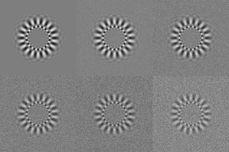
Example 4 CTF influence on images with noises
Usual images contain noises. Here, you will see if the CTF correction does work for such images.
Changes
### For mrcImageNoiseAdd
#NSRATIO=0
NSRATIO=0.5
Siemens Star (Step)
|
original_image |
Before_CTF_correction_with_noises(reversed contrast) |
After_CTF_correction |
Siemens Star (Cos)
Changes
### For mrcImageSiemensStar
#SSTAR_SHAPE=0
SSTAR_SHAPE=1
|
original_image(no noises) |
Before_CTF_correction_with_noises(reversed contrast) |
After_CTF_correction |
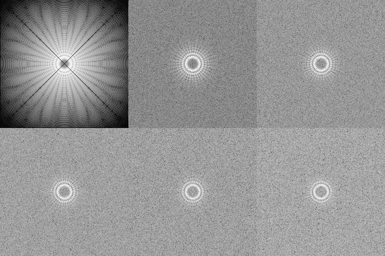
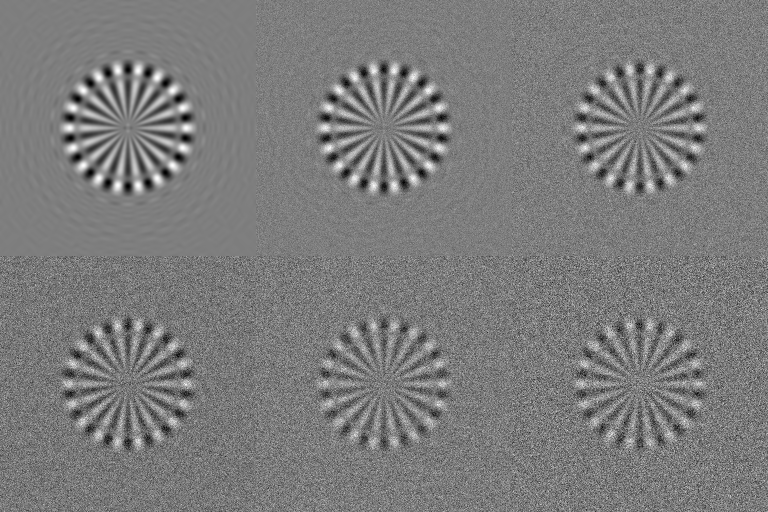
NS ratio influence =
Using this Makefile, images with the increasingly larger NS ratio are shown.
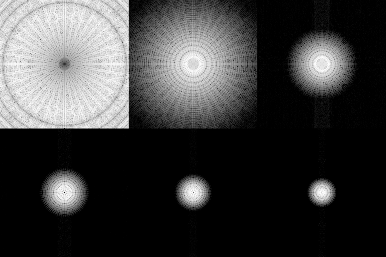
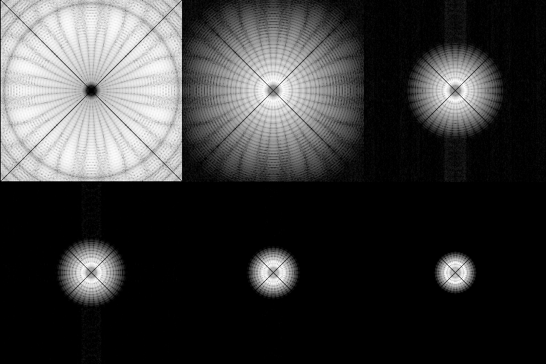
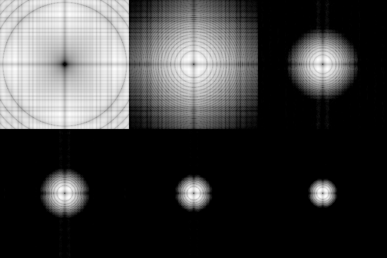
FFT images show that noises make the outer data unclear. This is because the high frequency components are affected more by noises, which are frequency independent. The original noise-free image has less of high frequency components (more low-frequency components). This makes it difficult to restore the high frequency components by the CTF correction, when there are high noises in the image.
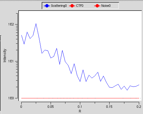
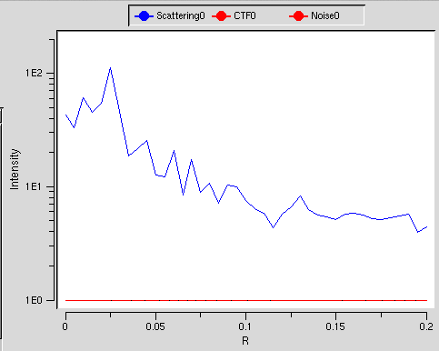
frequency components comparison between noise plus & minus(ctfDisplay)
In ctfDisplay, noise-plus graph has more intensities over the whole frequencies than the noise-free graph.
Example 5 defocus influence on images
The images of a field with different amount of defocus are shown.
Run example
We will see how the images change when their defocus amount is increased gradually. Gross shapes correspond to the low frequency components, while fine details correspond to the high frequency components. This will help you to understand the image differences over different amounts of defocus.
File contents
Makefile1 and Makefile2 are used. Those files use Makefiles in the example 1 and 2. The example 1 file is renamed as Makefile.common、and the example 1 file is renamed as Makefile.common2. Both files are put in the same directory. The Makefile in the example 5 is changes as follows.
#### INCLUDE ####
#-include ../../TIPS/LoopCommand/Makefile.config
#-include ../CTFCorrection2/Makefile
-include Makefile.config
-include Makefile.common2
The command below will do steps from the image creation to CTF correction for the images with a defocus range of 0 ~ 54000.
make all4
Siemens star (step)
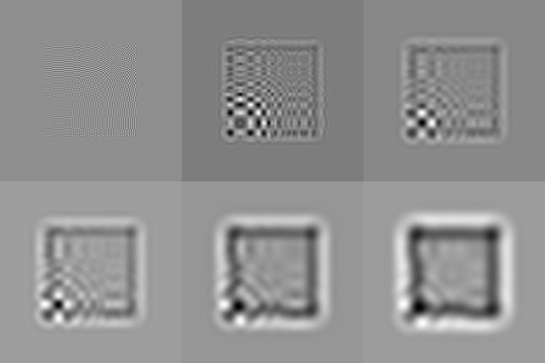
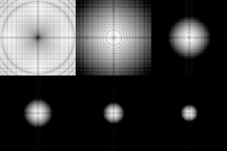
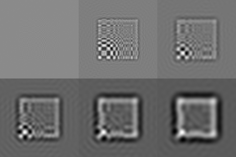
The images are shown for defocus 0 ~ 54000, when the CTF, FFT, CTF corrections are done.
Siemens star (Cos)
Changes in Makefile.common2
### For mrcImageSiemensStar
#SSTAR_SHAPE=0
SSTAR_SHAPE=1
do similarly
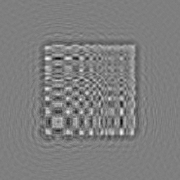
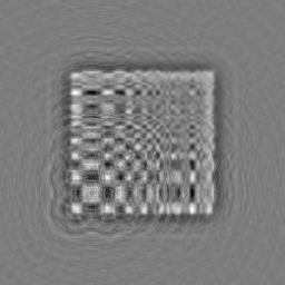
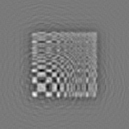
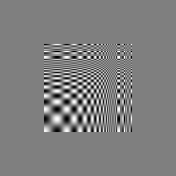
When the amount of defocus is increased, the grey ring after the CTF correction gets larger, the inside the ring (representing high frequency components) gets blurred and the outside gets clearer (with a higher contrast) more or less. With excessively large defocus, a black and white pattern outside the original image appears (a false feature) . FFT images show that the increased defocus reduces high frequency components.
Linear (Step)
Changes in Makefile.common2
### For mrcImageSiemensStar
#SSTAR_SHAPE=0
SSTAR_SHAPE=2
do similarly
Linear (Cos)
Changes in Makefile.common2
### For mrcImageSiemensStar
#SSTAR_SHAPE=0
SSTAR_SHAPE=3
do similarly
As increased degree of defocus deprives high frequency components, the CTF correction is not effective in restoring high resolution details.
Example 6 Averaging of images with different amounts of defocus
We will see the effect of averaging images (of the same field) with different amounts of defocus For this purpose, mrcImageMultiCTFCompensation command is used for making the averaged image. As this command uses a weighting incorporating the CTF effect for averaging, it reproduces finer details than the mrcImageAverage command which does a simple averaging.
File contents
this Makefile is used. tutorial/CTFCorrection/CTFCorrection5/ directory is the working directory.
Run example
The following commands calculate the images with different amounts of defocus from a Siemens star image, and then applies the CTF correction (for each image, ctfDisplay is called. This is the same as before).
make InitialSiemensStar
make ProcessForInput
make ProcessForInput2
make TIF2CTF2
Then the the following command outputs the averaged image of the two correctd images.
make ImageAverage
The following command does CTF correction against plural images.
make MULTICTF
The following command prints the CTF corrected image in the tiff format.
CTF2TIFF
Siemens star (step)
|
|
|
|
In the two cases, the interpolation is done by averaging. However,mrcImageMultiCTFCompensation gives the clearer image.
Siemens star (Cos)
Changes in Makefile
### For mrcImageSiemensStar
#SSTAR_SHAPE=0
SSTAR_SHAPE=1
do similarly
|
|
|
|
By averging the CTF corrected images, we get an image with clearer black-and white patterns up to the center.
Linear (step)
Changes in Makefile.common2
### For mrcImageSiemensStar
#SSTAR_SHAPE=0
SSTAR_SHAPE=2
do similarly
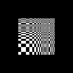
|
|
|
|
The averaging makes the images closer to the original
Linear (Cos)
Changes in Makefile.common2
### For mrcImageSiemensStar
#SSTAR_SHAPE=0
SSTAR_SHAPE=3
do similarly
|
|
|
|
Example 7 Averaging of images with different amount of defocus 2
The same comparison will be made using a different image file.
Run example
We use here the Makefile used in the example 5 input file in the example 2 (renamed as Input.inimrc) for running of the following commands.
make InitialCTFDataFromMRC
make ProcessForInput
make ProcessForInput2
make TIF2CTF2
make Input.tiff
make Input-2.tiff
make ImageAverage
|
|
By averaging the corrected images, the resultant image gets closer to the original image with respect to the white dots in the right-hand side and the structure of the white dot in the center lower part.
Others
More than one CTF-compensation programs are available in addition to Eos. They are as follows: • CTFFIND
