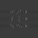
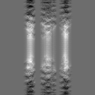
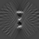
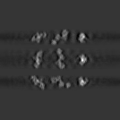
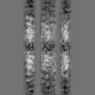
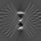
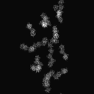
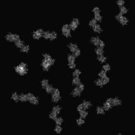
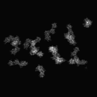
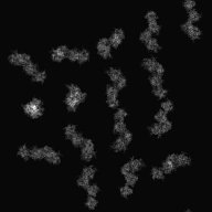
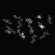
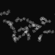
Difference between revisions of "Electron Tomography"
(→case of using mrcImageCorrelation) |
(→take tilt-series images) |
||
| (31 intermediate revisions by the same user not shown) | |||
| Line 10: | Line 10: | ||
<tr> | <tr> | ||
<td>[[File:Input-Tomogram1.png]]<br> | <td>[[File:Input-Tomogram1.png]]<br> | ||
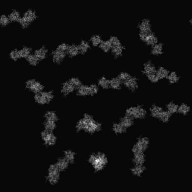
| − | <p align="Center">1 Axis Tilt(Center is | + | <p align="Center">1 Axis Tilt(Center is untilted image)<br></p> |
</td> | </td> | ||
</tr> | </tr> | ||
| Line 20: | Line 20: | ||
<tr> | <tr> | ||
<td>[[File:Input-Tomogram2.png]]<br> | <td>[[File:Input-Tomogram2.png]]<br> | ||
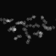
| − | <p align="Center">2 Axis Tilt(Center is | + | <p align="Center">2 Axis Tilt(Center is untilted image)(as 90° rotation image for 1 Axis Tilt's image)<br></p> |
</td> | </td> | ||
</tr> | </tr> | ||
| Line 33: | Line 33: | ||
Align roughly each tilt image by using the correlation among images around center. | Align roughly each tilt image by using the correlation among images around center. | ||
| − | <div>[[Media:1WDC-Tom-2dSet.zip|Input file]]( | + | <div>[[Media:1WDC-Tom-2dSet.zip|Input file]](tilt at range: ±60°, interval: 2°, around Y-axis)<br> |
<table> | <table> | ||
<tr> | <tr> | ||
| Line 121: | Line 121: | ||
== [[Fine Alignment]] == | == [[Fine Alignment]] == | ||
| − | <div> | + | <div> Align the position and the angle of tilt axis as possible.</div> |
<br> | <br> | ||
| − | === | + | ===Example 1(Alignment of tilt axis)=== |
| − | <div> | + | <div> Calculate tilt of axis by using [[mrcImageTiltAxisSearch]].</div> |
<br> | <br> | ||
| − | <div>[[Media:1WDC-Tom-Tilt-2dSet.zip|Input file]]( | + | <div>[[Media:1WDC-Tom-Tilt-2dSet.zip|Input file]](1 axis tilt data whose axis is tilted by 10 degree)<br> |
<table> | <table> | ||
<tr> | <tr> | ||
<td><p align="Center">[[File:1WDC-Tom-Tilt-2dSet.png]]<br> | <td><p align="Center">[[File:1WDC-Tom-Tilt-2dSet.png]]<br> | ||
| − | + | 10° interval<br></p> | |
</td> | </td> | ||
</tr> | </tr> | ||
| Line 138: | Line 138: | ||
<br> | <br> | ||
| − | <div>[[Media:Makefile-Tomogram1.zip| | + | <div>[[Media:Makefile-Tomogram1.zip|Used Makefile]]'s Setting</div> |
<pre> | <pre> | ||
# RotMode | # RotMode | ||
| Line 166: | Line 166: | ||
<br> | <br> | ||
| − | <div> | + | <div>Command</div> |
<pre> | <pre> | ||
make TiltFit | make TiltFit | ||
| Line 172: | Line 172: | ||
<br> | <br> | ||
| − | <div> | + | <div>Output of axis tilt(It is stored at .tiltinfofile)</div> |
<pre> | <pre> | ||
9.895 | 9.895 | ||
| Line 178: | Line 178: | ||
<br> | <br> | ||
| − | <div> | + | <div>difference about 3D Reconstruction</div> |
<table> | <table> | ||
<tr> | <tr> | ||
| − | <td> | + | <td>Before correction</td> |
</tr> | </tr> | ||
<tr> | <tr> | ||
| Line 189: | Line 189: | ||
</tr> | </tr> | ||
<tr> | <tr> | ||
| − | <td> | + | <td>After correction</td> |
</tr> | </tr> | ||
<tr> | <tr> | ||
| Line 204: | Line 204: | ||
<br> | <br> | ||
| − | === | + | ===Example2(Repeatedly Alignment of tilt axis)=== |
| − | <div> | + | <div>Repeat to use [[mrcImageTiltAxisSearch]], referring tilt of output axis.</div> |
<br> | <br> | ||
| − | <div>[[Media:1WDC-Tom-Tilt1-2dSet.zip|Input file]]( | + | <div>[[Media:1WDC-Tom-Tilt1-2dSet.zip|Input file]](1 axis tilt data whose axis is tilted by 1 degree)<br> |
<table> | <table> | ||
<tr> | <tr> | ||
<td><p align="Center">[[File:1WDC-Tom-Tilt1-2dSet.png]]<br> | <td><p align="Center">[[File:1WDC-Tom-Tilt1-2dSet.png]]<br> | ||
| − | + | 10° interval<br></p> | |
</td> | </td> | ||
</tr> | </tr> | ||
| Line 218: | Line 218: | ||
<br> | <br> | ||
| − | <div>[[Media:Makefile-Tomogram2.zip| | + | <div>[[Media:Makefile-Tomogram2.zip|Used Makefile]]'s Setting</div> |
<pre> | <pre> | ||
# For mrcImageTiltAxisSearch | # For mrcImageTiltAxisSearch | ||
| Line 245: | Line 245: | ||
<br> | <br> | ||
| − | <div> | + | <div>Command</div> |
<pre> | <pre> | ||
make TiltFit | make TiltFit | ||
| Line 251: | Line 251: | ||
<br> | <br> | ||
| − | <div> | + | <div>transition of tilt of axis</div> |
<pre> | <pre> | ||
0.084 | 0.084 | ||
| Line 267: | Line 267: | ||
0.701 | 0.701 | ||
</pre> | </pre> | ||
| − | <div> | + | <div>The tilt of axis approaches gradually 1.</div> |
<br> | <br> | ||
== [[3D Reconstruction]] == | == [[3D Reconstruction]] == | ||
| − | <div> | + | <div> Reconstruct 3D image from 2D image set.</div> |
<br> | <br> | ||
| − | <div>[[Media:1WDC-shift1.3d| | + | <div>[[Media:1WDC-shift1.3d|Original 3D data]]'s image</div> |
<table> | <table> | ||
<tr> | <tr> | ||
| Line 303: | Line 303: | ||
===[[mrc2Dto3D]]=== | ===[[mrc2Dto3D]]=== | ||
| − | ==== | + | ====Example1 (Reconstruction of 1 axis tilt)==== |
| − | <div> | + | <div> If the tilt axis don't deviate, set the angle information directly to input file list.</div> |
<br> | <br> | ||
| Line 311: | Line 311: | ||
<tr> | <tr> | ||
<td><p align="Center">[[File:1WDC-Tom-Fit-2d.png]]<br> | <td><p align="Center">[[File:1WDC-Tom-Fit-2d.png]]<br> | ||
| − | + | 10° interval<br></p> | |
</td> | </td> | ||
</tr> | </tr> | ||
| Line 317: | Line 317: | ||
<br> | <br> | ||
| − | <div> | + | <div>Command: [[mrc2Dto3D]] -i Input.3dlst -o Input.3d -m 1</div> |
<br> | <br> | ||
| − | <div>[[Media:Makefile-Tomogram.zip| | + | <div>By using [[Media:Makefile-Tomogram.zip|This Makefile]], perform the following command for reconstruction.</div> |
| − | <div> | + | <div>Setting data</div> |
<pre> | <pre> | ||
# For Reconstruction | # For Reconstruction | ||
| Line 338: | Line 338: | ||
ROT3MAX=0 | ROT3MAX=0 | ||
</pre> | </pre> | ||
| − | <div> | + | <div>Command</div> |
<pre> | <pre> | ||
make 3DList | make 3DList | ||
| Line 373: | Line 373: | ||
<br> | <br> | ||
| − | ==== | + | ====Example2 (Reconstruction of 2 axis tilt)==== |
| − | <div> | + | <div>Perform 3D Reconstruction for images of 2 axis tilt.</div> |
| − | <div>[[Media:1WDC-Tom1-2dSet.zip|Input file]](X, Y- | + | <div>[[Media:1WDC-Tom1-2dSet.zip|Input file]](tilt at range: each ±60°, interval: each 10°, around X, Y-axis))<br> |
<table> | <table> | ||
<tr> | <tr> | ||
<td><p align="Center">[[File:1WDC-Tom1-2dSet.png]]<br> | <td><p align="Center">[[File:1WDC-Tom1-2dSet.png]]<br> | ||
| − | + | 1st line is X-axis tilt, 2nd line is Y-axis tilt<br></p> | |
</td> | </td> | ||
</tr> | </tr> | ||
| Line 385: | Line 385: | ||
<br> | <br> | ||
| − | <div>[[Media:Makefile-Tomogram6.zip| | + | <div>By using [[Media:Makefile-Tomogram6.zip|This Makefile]], perform 3D Reconstruction.</div> |
| − | <div> | + | <div>Command</div> |
<pre> | <pre> | ||
make all | make all | ||
| Line 392: | Line 392: | ||
<br> | <br> | ||
| − | <div> | + | <div>Halfway, X runs for determine essential part of image. This time, select whole field and save to ROI information.<br> |
| − | + | Output Information file</div> | |
<pre> | <pre> | ||
DataA_006.mrcsmth-0000.roi Rect 0.000000 0.000000 63.000000 0.000000 63.000000 63.000000 0.000000 63.000000 | DataA_006.mrcsmth-0000.roi Rect 0.000000 0.000000 63.000000 0.000000 63.000000 63.000000 0.000000 63.000000 | ||
| Line 427: | Line 427: | ||
<br> | <br> | ||
| − | ==== | + | ====Example3 (Reconstruction of 2 axis tilt with Double)==== |
| − | <div>[[mrc2Dto3D]] | + | <div>By using [[mrc2Dto3D]]'s Option -Double, perform 3D Reconstruction.</div> |
<br> | <br> | ||
| − | <div> | + | <div>Changed part</div> |
<pre> | <pre> | ||
.roilst.mrc3d: | .roilst.mrc3d: | ||
| Line 467: | Line 467: | ||
<br> | <br> | ||
| − | === | + | ===3D Reconstruction with Radon Transform)=== |
| − | <div> | + | <div> Radon Transform can perform 3D reconstruction without using [[mrc2Dto3D]]. Perform as the Following. |
<br> | <br> | ||
| − | + | Aligned 2D image list<br> | |
↓[[mrcImageSinogramCreate]]<br> | ↓[[mrcImageSinogramCreate]]<br> | ||
| − | + | Sinogram list<br> | |
↓[[mrcRadon2Dto3D]]<br> | ↓[[mrcRadon2Dto3D]]<br> | ||
| − | + | 3D Radon file<br> | |
↓[[mrcImageInverseRadonTransform]]<br> | ↓[[mrcImageInverseRadonTransform]]<br> | ||
| − | + | 3D file (Finished)</div> | |
<br> | <br> | ||
| − | ==== | + | ====Example 1==== |
| − | <div>[[Media:Makefile-Tomogram7.zip| | + | <div>Use [[Media:Makefile-Tomogram7.zip|This Makefile]] and Input is [[Media:1WDC-Tom2-2dSet.zip|.roilstfile by Example2]].</div> |
<br> | <br> | ||
| − | <div> | + | <div>Command</div> |
<pre> | <pre> | ||
make Radon3D | make Radon3D | ||
| Line 520: | Line 520: | ||
<br> | <br> | ||
| − | ==== | + | ====Example2==== |
| − | <div> | + | <div> Use [[Media:Makefile-Tomogram7.zip|This Makefile]] changing option of Inverse Radon Transform.</div> |
<br> | <br> | ||
| − | <div> | + | <div>Changed part</div> |
<pre> | <pre> | ||
### RadonTransform | ### RadonTransform | ||
| Line 531: | Line 531: | ||
</pre> | </pre> | ||
| − | <div> | + | <div>Command</div> |
<pre> | <pre> | ||
make Radon3D | make Radon3D | ||
| Line 568: | Line 568: | ||
== [[Problems of Electron Tomography image]] == | == [[Problems of Electron Tomography image]] == | ||
| − | === | + | ===Missing Area=== |
| − | <div> | + | <div> Reconstructed image don't have enough angle data, so it have the region that doesn't have information called "Missing Area" (1-Axis: Wedge, 2-Axis: Pyramid). Thus, it has a Blur depending on angle.</div> |
<br> | <br> | ||
| − | <div>[[:Media:Makefile-Tomogram5.zip| | + | <div>[[:Media:Makefile-Tomogram5.zip|Used MakeFile]].</div> |
| − | <div>[[:Media:Input-ellipsoidal.3d| | + | <div>[[:Media:Input-ellipsoidal.3d|Original 3D image]](rename to Target.ini3d)</div> |
<table> | <table> | ||
<tr> | <tr> | ||
| Line 601: | Line 601: | ||
<br> | <br> | ||
| − | <div> | + | <div>3D Reconstruction of Projection image of 1 Axis Tilt(Y-axis: -60° ~ 60°: 10° interval)</div> |
| − | <div> | + | <div>Changed part</div> |
<pre> | <pre> | ||
TILTAXISNUMBER=1 # Single: 1 Double: 2 | TILTAXISNUMBER=1 # Single: 1 Double: 2 | ||
| Line 608: | Line 608: | ||
<br> | <br> | ||
| − | <div> | + | <div>Command</div> |
<pre> | <pre> | ||
make Target.ini2d | make Target.ini2d | ||
| Line 643: | Line 643: | ||
<br> | <br> | ||
| − | <div> | + | <div>3D Reconstruction of Projection image of 2 Axis Tilt(X, Y-axis: -60° ~ 60°: 10° interval)</div> |
| − | <div> | + | <div>Changed part</div> |
<pre> | <pre> | ||
TILTAXISNUMBER=2 # Single: 1 Double: 2 | TILTAXISNUMBER=2 # Single: 1 Double: 2 | ||
</pre> | </pre> | ||
| − | <div> | + | <div>Command</div> |
<pre> | <pre> | ||
make Target.ini2d1 | make Target.ini2d1 | ||
| Line 683: | Line 683: | ||
<br> | <br> | ||
| − | === | + | ===Problem of position and focus of image=== |
| − | <div> | + | <div> Because sample is taken being gradually tilted, the distance between it and lens is change as well. Thus, how to correct is one of the point.</div> |
<br> | <br> | ||
| − | ====parallel | + | ====Correction of parallel transform==== |
| − | <div> | + | <div> As tilt angle is large, the photo field is wide, and the sample approaches tilt axis. For this correction, calculate the distance of parallel shift by using [[mrcImageCorrelation]]. In addition, compare between near images, because these shape change depending on tilt of sample</div> |
<br> | <br> | ||
| − | ==== | + | ====Determine axis==== |
| − | <div> | + | <div> Tomogram does not always tilt around set axis. Because it has a little error depending on several factors as performance of electron microscopy or situation of sample. Speaking about error of tilt axis, [[mrcImageTiltAxisSearch]] can calculate it.</div> |
<br> | <br> | ||
| − | == | + | == Image Process for Tomograph == |
| − | <div> | + | <div> Perform the following preprocesses for analysis of reconstructed 3D image.</div> |
<br> | <br> | ||
=== Smoothing === | === Smoothing === | ||
| − | <div> | + | <div> Perform the smoothing for noise removing of reconstructed 3D image.</div> |
<br> | <br> | ||
| − | ==== | + | ====Example1==== |
<div>[[Media:Input-Tomogram3D.mrc|Input file]]</div> | <div>[[Media:Input-Tomogram3D.mrc|Input file]]</div> | ||
<table> | <table> | ||
| Line 732: | Line 732: | ||
<br> | <br> | ||
| − | <div> | + | <div>Command: [[mrcImageSmoothing]] -i Input-Tomogram3D.mrc -o Input-TomogramSmth.mrc -m 1</div> |
<br> | <br> | ||
| Line 763: | Line 763: | ||
<br> | <br> | ||
| − | === | + | === Segmentation === |
| − | + | Because tomogram contains a variety of structures, it requires tasks such as cutting out a segment of interest from the 3D image. Support software is required for it. There is cutting out from 2D image in some cases.<br> | |
<br> | <br> | ||
| − | ==== | + | ====Cut out 3D image==== |
| − | <div> | + | <div> Cut out parts that is determined as particle from reconstructed 3D image. Cut out data is used by 3D image analysis or average.</div> |
<br> | <br> | ||
| − | ===== | + | =====Example1===== |
| − | <div> | + | <div>If the width and the coordinates of the part to be cut has been found, you can use [[mrcImageCenterGet]].</div> |
<br> | <br> | ||
| Line 803: | Line 803: | ||
<br> | <br> | ||
| − | <div> | + | <div>Command: [[mrcImageCenterGet]] -i Input-TomogramSmth.mrc -o Input-TomogramSub.mrc -Cx 67 -Cy 67 -Cz 67 -Nx 27 -Ny 27 -Nz 27</div> |
<br> | <br> | ||
| Line 834: | Line 834: | ||
<br> | <br> | ||
| − | ==== | + | ====Cut out 2D image==== |
| − | <div> | + | <div> If a target of reconstruction is not whole photo field but a part of field, there is a case to cut out partially 2D image from tilt image. It is low cost than reconstruction of whole. Therefore this method is used in case of not needing whole data. Because samples are taken being tilted gradually, coordinates and angles need to be changed for each image. Cut out by using [[mrcImageCenterGet]], [[mrcImageROI]], [[mrcImageROIs]] and so on. It takes significant time that all parts are cut out. Thus, it takes how to calculate and cut out automatically other tilted image by deciding manually cut out of range in the reference(untilted) image.</div> |
| − | + | Operation movie: [[:Media:Tomography4-1.mov|(.mov)]] [[:Media:Tomography4-1.mp4|(.mp4)]]<br> | |
<br> | <br> | ||
| − | <div> | + | <div>Perform 3D Reconstruction as the following.</div> |
<pre> | <pre> | ||
| − | + | Tilted Image(Multiple 2D images)(Prepared) | |
| − | ↓ | + | ↓ Set range of cutting out.(Display2: untilted image only) |
| − | + | Information file for cutting out untilted image(ROIInformation) | |
| − | ↓ | + | ↓ Calculate the range of cutting out tilted images.(Currently, Makefile performs this process.) |
| − | + | Information file for cutting out each tilted image | |
| − | ↓ | + | ↓ Cut out images(mrcImageROIs) |
| − | + | Multiple cut out image files(Number of cutting out × Number of tilted image) | |
| − | ↓ | + | ↓ Alignment(mrcImageCorrelarion + Makefile's process) |
| − | + | Aligned information file for cutting out (Number of tilted image) | |
| − | ↓ | + | ↓ Cut out images again.(mrcImageROIs) (* It resets the position and cut out them.) |
| − | + | Aligned image(ROI)file(Number of cutting out × Number of tilted image) | |
| − | ↓ | + | ↓ Create Angle Information file.(Makefile performs this process.) |
| − | + | Angle Information file(Number of cutting out) | |
| − | ↓ | + | ↓ 3D Reconstruction(mrc2Dto3D) |
| − | + | 3D image(Number of cutting out) | |
</pre> | </pre> | ||
| − | ===== | + | =====Example1(Subtomogram of 1 axis tilt)===== |
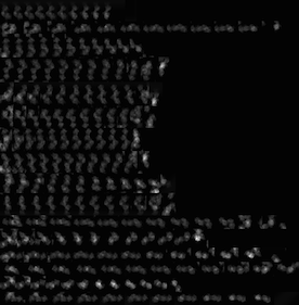
| − | <div>[[Media:Input-Tomogram2DSet1.zip|Input file]]'s image( | + | <div>[[Media:Input-Tomogram2DSet1.zip|Input file]]'s image(parts)(y-axis tilt: -60° ~ 60°: 2° interval)</div> |
<table> | <table> | ||
<tr> | <tr> | ||
| Line 889: | Line 889: | ||
<br> | <br> | ||
| − | <div>[[:Media:Makefile-Tomogram4.zip| | + | <div>Use [[:Media:Makefile-Tomogram4.zip|This Makefile]].</div> |
| − | <div> | + | <div>Command</div> |
<pre> | <pre> | ||
make all | make all | ||
</pre> | </pre> | ||
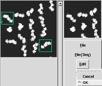
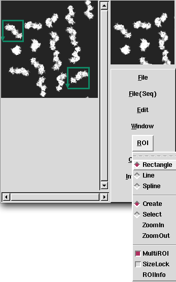
| − | <div> | + | <div>After input the command, [[Display2]](2D viewer) is opened, then select ranges of cutting out, and create the Information file(.roiinfo).</div> |
<table> | <table> | ||
<tr> | <tr> | ||
| Line 902: | Line 902: | ||
</tr> | </tr> | ||
<tr> | <tr> | ||
| − | <td><p align="Center"> | + | <td><p align="Center">Select ranges of cutting out, and determine by Edit->OK.</p></td> |
| − | <td><p align="Center"> | + | <td><p align="Center">If you wish to cut out multiple images, select ROI->MultiROI.</p> </td> |
</tr> | </tr> | ||
</table> | </table> | ||
| Line 911: | Line 911: | ||
</tr> | </tr> | ||
<tr> | <tr> | ||
| − | <td> | + | <td>This time, Extracting "Information" only is enough for automatically cutting out.<br> |
| − | ROI | + | Push the save button that is right side of "InfoFileName" on "ROI Information" window, then the file is created.<br> |
| − | ( | + | (Or set "Information" for "ExtractMode", and push the "Extract" button.)</td> |
</tr> | </tr> | ||
</table> | </table> | ||
<br> | <br> | ||
| − | <div> | + | <div>Output Information file in this time.</div> |
<pre> | <pre> | ||
p1_031-0000.roi Rect 20 30 60 30 60 70 20 70 | p1_031-0000.roi Rect 20 30 60 30 60 70 20 70 | ||
| Line 939: | Line 939: | ||
<br> | <br> | ||
| − | <div> | + | <div>When you create Information file(.roiinfo) for one image by [[Display2]], it calculates automatically other image's range, and cuts out them.</div> |
<br> | <br> | ||
| − | <div> | + | <div>cut out automatically images(columns: each selected range, rows: each file(angle))(.pad)</div> |
<table> | <table> | ||
<tr> | <tr> | ||
| Line 956: | Line 956: | ||
<br> | <br> | ||
| − | <div> | + | <div>After cutting out, it performs 3D Reconstruction for each image.</div> |
<br> | <br> | ||
| − | <div> | + | <div>Reconstructed 3D images(.mrc3d)</div> |
<table> | <table> | ||
<tr> | <tr> | ||
| Line 976: | Line 976: | ||
<br> | <br> | ||
| − | ===== | + | =====Example2(Subtomogram of 2 axis tilt)===== |
| − | <div> | + | <div> Perform cutting out and reconstruction from 2 axis tilted images.</div> |
<br> | <br> | ||
| − | <div>[[Media:Input-Tomogram2DSet2.zip|Input file]]'s | + | <div>[[Media:Input-Tomogram2DSet2.zip|Input file]]'s images(parts)(x-axis, y-axis tilt: -60° ~ 60°: 10° interval)</div> |
<table> | <table> | ||
<tr> | <tr> | ||
| − | <td>x- | + | <td>x-axis tilt</td> |
<td><p align="Center">[[File:Input-Tomogram2DSet2.png]]<br> | <td><p align="Center">[[File:Input-Tomogram2DSet2.png]]<br> | ||
-60°<br></p> | -60°<br></p> | ||
| Line 995: | Line 995: | ||
</tr> | </tr> | ||
<tr> | <tr> | ||
| − | <td>y- | + | <td>y-axis tilt</td> |
<td><p align="Center">[[File:Input3-Tomogram2DSet2.png]]<br> | <td><p align="Center">[[File:Input3-Tomogram2DSet2.png]]<br> | ||
-60°<br></p> | -60°<br></p> | ||
| Line 1,009: | Line 1,009: | ||
<br> | <br> | ||
| − | <div>[[:Media:Makefile-Tomogram5.zip| | + | <div>Use [[:Media:Makefile-Tomogram5.zip|This Makefile]].</div> |
<br> | <br> | ||
| − | <div> | + | <div>Command</div> |
<pre> | <pre> | ||
make all | make all | ||
| Line 1,018: | Line 1,018: | ||
<br> | <br> | ||
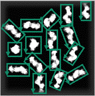
| − | <div> | + | <div>This time, cut out ROI files about these regions.</div> |
<div>[[File:Tomogram2-Segmanetation.png]]</div> | <div>[[File:Tomogram2-Segmanetation.png]]</div> | ||
| − | <div> | + | <div>Output Information files</div> |
<pre> | <pre> | ||
DataA_006-0000.roi Rect 0.722314 137.147614 33.000000 106.000000 49.053597 122.636041 16.775911 153.783654 | DataA_006-0000.roi Rect 0.722314 137.147614 33.000000 106.000000 49.053597 122.636041 16.775911 153.783654 | ||
| Line 1,042: | Line 1,042: | ||
<br> | <br> | ||
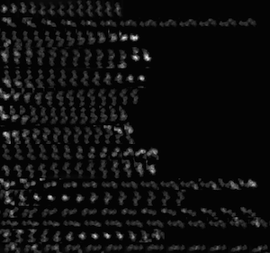
| − | <div> | + | <div>cut out automatically images(columns: each selected range, rows: each file(angle))(.pad)</div> |
<table> | <table> | ||
<tr> | <tr> | ||
<td><p align="Center">[[File:Tomogram2-Segmanetation1.png]]<br> | <td><p align="Center">[[File:Tomogram2-Segmanetation1.png]]<br> | ||
| − | DataA(x- | + | DataA(x-axis tilt)<br></p> |
</td> | </td> | ||
<td><p align="Center">[[File:Tomogram2-Segmanetation2.png]]<br> | <td><p align="Center">[[File:Tomogram2-Segmanetation2.png]]<br> | ||
| − | DataB(y- | + | DataB(y-axis tilt)<br></p> |
</td> | </td> | ||
</tr> | </tr> | ||
</table> | </table> | ||
| − | <div> | + | <div>ROI files have been cut out automatically for each tilt axis. (It is not easy that each of parts is found, because each size are different...)</div> |
<br> | <br> | ||
| − | <div> | + | <div>Reconstructed 3D images(.mrc3d)</div> |
<table> | <table> | ||
<tr> | <tr> | ||
| Line 1,074: | Line 1,074: | ||
== [[Interpretation of 3D Reconstruction]] == | == [[Interpretation of 3D Reconstruction]] == | ||
| − | + | ||
=== [[Averaging of Subtomograms]]=== | === [[Averaging of Subtomograms]]=== | ||
| − | <div> | + | <div> If each 3D data that is divided by segmentation is same particle and have different angle, these average image interpolates these "Missing Area", and makes more correct 3D image.</div> |
<br> | <br> | ||
| − | <div> | + | <div>Divided data1</div> |
<table> | <table> | ||
<tr> | <tr> | ||
| Line 1,088: | Line 1,088: | ||
</tr> | </tr> | ||
</table> | </table> | ||
| − | <div> | + | <div>Divided data2(90° rotation)</div> |
<table> | <table> | ||
<tr> | <tr> | ||
| Line 1,096: | Line 1,096: | ||
</tr> | </tr> | ||
</table> | </table> | ||
| − | <div> | + | <div>Average data</div> |
<table> | <table> | ||
<tr> | <tr> | ||
| Line 1,111: | Line 1,111: | ||
<br> | <br> | ||
| − | ==== | + | ====Example1==== |
<div>[[Media:Input-Mean-SubTomogram.zip|Input file]]</div> | <div>[[Media:Input-Mean-SubTomogram.zip|Input file]]</div> | ||
<table> | <table> | ||
| Line 1,129: | Line 1,129: | ||
<br> | <br> | ||
| − | <div> | + | <div>align by using [[mrcImageAutoRotationCorrelation3D]] before averaging 3D image.</div> |
<br> | <br> | ||
| − | <div>[[Media:Input-TomogramSub.mrc|Reference file]](Input | + | <div>[[Media:Input-TomogramSub.mrc|Reference file]](Center data of Input file)</div> |
<table> | <table> | ||
<tr> | <tr> | ||
| Line 1,160: | Line 1,160: | ||
<br> | <br> | ||
| − | <div> | + | <div>Command: [[mrcImageAutoRotationCorrelation3D]] -i c1-1.mrc -r c2-2.mrc -fit f1-1.mrc -EA YOYS -Rot1 0 0 30 -Rot2 0 330 30 -Rot3 0 330 30 -Xrange 0 0 -Yrange 0 0 -Zrange 0 0 </div> |
<br> | <br> | ||
| − | <div>[[Media:Input-Fit-SubTomogram.zip| | + | <div>[[Media:Input-Fit-SubTomogram.zip|corrected data]](-fit 's Output file)</div> |
<table> | <table> | ||
<tr> | <tr> | ||
| Line 1,180: | Line 1,180: | ||
<br> | <br> | ||
| − | <div> | + | <div>Perform Averaging of corrected files by [[mrcImageAverage]].</div> |
<div>Output file</div> | <div>Output file</div> | ||
<table> | <table> | ||
| Line 1,207: | Line 1,207: | ||
</tr> | </tr> | ||
</table> | </table> | ||
| − | <div> | + | <div>3D image's quality has been improved by averaging. (Particular, xy-plane)</div> |
<br> | <br> | ||
| − | ==== | + | ====Example2==== |
<div>[[Media:Outdata-Tomogram.zip|Input file]]</div> | <div>[[Media:Outdata-Tomogram.zip|Input file]]</div> | ||
<table> | <table> | ||
| Line 1,228: | Line 1,228: | ||
<br> | <br> | ||
| − | <div>[[Media:Input-TomogramSub1.mrc|Reference file]](Input | + | <div>[[Media:Input-TomogramSub1.mrc|Reference file]](Use top data of Input file)</div> |
<table> | <table> | ||
<tr> | <tr> | ||
| Line 1,256: | Line 1,256: | ||
<br> | <br> | ||
| − | <div> | + | <div>First, perform alignment as well.</div> |
| − | <div> | + | <div>Command: [[mrcImageAutoRotationCorrelation3D]] -i p1-0001.mrc3d -r Target.mrc3dref -fit p1-0001.3dfit -EA XEYR -Rot1 0 355 5 -Rot2 0 355 5 -Rot3 0 0 30 -M 18</div> |
<br> | <br> | ||
| − | <div>[[Media:Input-Fit-SubTomogram1.zip| | + | <div>[[Media:Input-Fit-SubTomogram1.zip|Corrected data]](-fit 's Output file)</div> |
<table> | <table> | ||
<tr> | <tr> | ||
| Line 1,276: | Line 1,276: | ||
<br> | <br> | ||
| − | <div> | + | <div>Some fits the reference file, and some are otherwise.<br> |
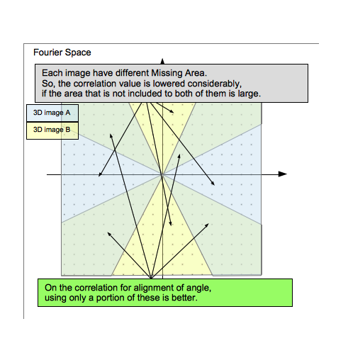
| − | + | Because each 3D subtomogram image has different "Missing Area". Thus the correlation value of the orientation that is included in not both of them is Considerably lower.</div> | |
<div>[[File:Fig-SubTomogram.png]]</div> | <div>[[File:Fig-SubTomogram.png]]</div> | ||
<br> | <br> | ||
| − | <div> | + | <div>Perform averaging of Corrected files by using [[mrcImageAverage]].</div> |
<div>Output file</div> | <div>Output file</div> | ||
<table> | <table> | ||
Latest revision as of 04:26, 29 September 2014
Electron Tomography is one of 3D Reconstruction using electron microscope. It is the method that reconstruct 3D image by electron micrographs which is projected the same photo field for several angle, then it creates Tomogram by using computer.
In the following, describe its method in order.
Contents
take tilt-series images
 1 Axis Tilt(Center is untilted image) |
 2 Axis Tilt(Center is untilted image)(as 90° rotation image for 1 Axis Tilt's image) |
Image Correction
Tilt-series image's defocus is larger than normal electron photograph's one, because it is taken as whole field is underfocus. In this case, CTF Correction is not required, because outside data of 1st thon ring don't have almost information if you use electron gun as LaB6. But, in the case of using field-emission electron gun (FEG), note that you might get a incorrect data.
Rough Alignment
Align roughly each tilt image by using the correlation among images around center.
Preprocess(Windowing)
# For Windowing
WIN_X=0.2
WIN_X_MAX=0.2
WIN_Y=0.1
WIN_Y_MAX=0.1
WIN_MODE=18
make Windowing
Alignment
e.g. case of images whose interval is 2 degree
Align 2° image to 0° image.
Align 4° image to Aligned 2° image.
Align 6° image to Aligned 4° image.
.
.
case of using mrcImageCorrelation
Example 1
make CorFit1
Fine Alignment
Example 1(Alignment of tilt axis)
# RotMode
ROTMODE=ZOYS
# Rot1
ROT1MIN=10
ROT1MAX=10
ROT1D=10
# Rot2
ROT2MIN=-60
ROT2MAX=60
ROT2D=2
# Rot3
ROT3MIN=0
ROT3MAX=0
ROT3D=30
### For mrcImageMove
SHIFT2MAX=10
SHIFT3MAX=0
### For mrcImageTiltAxisSearch
TILTMIN=0
TILTMAX=20
TILTN=10
TILTITER=1
TILTSCALE=5
make TiltFit
9.895
| Before correction | ||
 |
 |
 |
| After correction | ||
 |
 |
 |
| xy-plane | yz-plane | zx-plane |
Example2(Repeatedly Alignment of tilt axis)
# For mrcImageTiltAxisSearch
IN_TILT_EXT=roi
# RotMode
ROTMODE=ZEYR
# Rot1
ROT1MIN=1
ROT1MAX=1
ROT1D=1
# Rot2
ROT2MIN=-60
ROT2MAX=60
ROT2D=10
# Rot3
ROT3MIN=0
ROT3MAX=0
ROT3D=10
### For mrcImageTiltAxisSearch
TILTMIN=-10
TILTMAX=10
TILTN=10
TILTITER=100
TILTSCALE=5
make TiltFit
0.084
0.161
0.230
0.294
0.345

...

0.701
0.700
0.685
0.706
0.701
3D Reconstruction
Min Max |
0 (0, 0, 0) 4 (31, 26, 26) |
mrc2Dto3D
Example1 (Reconstruction of 1 axis tilt)
# For Reconstruction
IN_3D_EXT=fit
# RotMode
ROTMODE=YOYS
# Rot1
ROT1MIN=-60
ROT1MAX=60
ROT1D=2
# Rot2
ROT2MIN=0
ROT2MAX=0
# Rot3
ROT3MIN=0
ROT3MAX=0
make 3DList
make Input.3d
Min Max |
-0.00437076 (39, 34, 36) 0.00799233 (37, 34, 36) |
Example2 (Reconstruction of 2 axis tilt)
make all
Output Information file
DataA_006.mrcsmth-0000.roi Rect 0.000000 0.000000 63.000000 0.000000 63.000000 63.000000 0.000000 63.000000
Min Max |
-9.32199 (29, 37, 34) 21.995 (40, 35, 32) |
Example3 (Reconstruction of 2 axis tilt with Double)
.roilst.mrc3d:
#	mrc2Dto3D -I $*.roilst -o $*.mrc3d -single 0 -InterpolationMode 2 -m 1
	mrc2Dto3D -I $*.roilst -o $*.mrc3d -Double -InterpolationMode 2 -m 1
Min Max |
-10360.9 (41, 24, 0) 8132.05 (40, 35, 31) |
3D Reconstruction with Radon Transform)
Aligned 2D image list
↓mrcImageSinogramCreate
Sinogram list
↓mrcRadon2Dto3D
3D Radon file
↓mrcImageInverseRadonTransform
Example 1
make Radon3D
| xy-plane | yz-plane | zx-plane |
 |
 |
 |
Min Max |
1.84923e+06 (0, 59, 28) 1.17991e+07 (34, 31, 30) |
Example2
### RadonTransform
RBP_MODE=4
RBP_OPTION=-Rmin 0.05 -Rmax 0.1
make Radon3D
| xy-plane | yz-plane | zx-plane |
 |
 |
 |
Min Max |
-344789 (25, 25, 0) 631546 (37, 34, 28) |
Problems of Electron Tomography image
Missing Area
Min Max |
0 (0, 0, 0) 2 (29, 29, 14) |
TILTAXISNUMBER=1 # Single: 1 Double: 2
make Target.ini2d
make TestData2DSet
make all
Min Max |
-0.00330818 (52, 36, 32) 0.00425516 (13, 37, 32) |
TILTAXISNUMBER=2 # Single: 1 Double: 2
make Target.ini2d1
make TestData2DSetDouble
make all
Min Max |
-0.00248567 (12, 38, 32) 0.00344027 (13, 37, 32) |
Problem of position and focus of image
Correction of parallel transform
Determine axis
Image Process for Tomograph
Smoothing
Example1
Min Max |
-0.00268221 (76, 92, 66) 0.00642324 (89, 42, 71) |
Min Max |
-0.00136636 (75, 42, 133) 0.00292404 (94, 65, 68) |
Segmentation
Because tomogram contains a variety of structures, it requires tasks such as cutting out a segment of interest from the 3D image. Support software is required for it. There is cutting out from 2D image in some cases.
Cut out 3D image
Example1
Min Max |
-0.00136636 (75, 42, 133) 0.00292404 (94, 65, 68) |
Min Max |
-0.0012017 (5, 9, 13) 0.00263957 (13, 6, 15) |
Cut out 2D image
Operation movie: (.mov) (.mp4)
Tilted Image(Multiple 2D images)(Prepared)

↓	Set range of cutting out.(Display2: untilted image only)

Information file for cutting out untilted image(ROIInformation)

↓	Calculate the range of cutting out tilted images.(Currently, Makefile performs this process.)

Information file for cutting out each tilted image

↓	Cut out images(mrcImageROIs)

Multiple cut out image files(Number of cutting out × Number of tilted image)

↓	Alignment(mrcImageCorrelarion + Makefile's process)

Aligned information file for cutting out (Number of tilted image)

↓	Cut out images again.(mrcImageROIs) (* It resets the position and cut out them.)

Aligned image(ROI)file(Number of cutting out × Number of tilted image)

↓	Create Angle Information file.(Makefile performs this process.)

Angle Information file(Number of cutting out)

↓	3D Reconstruction(mrc2Dto3D)

3D image(Number of cutting out)
Example1(Subtomogram of 1 axis tilt)
make all
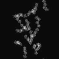
Select ranges of cutting out, and determine by Edit->OK. |
If you wish to cut out multiple images, select ROI->MultiROI. |
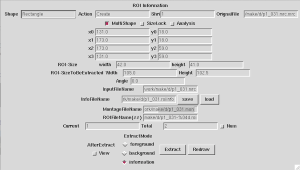
| This time, Extracting "Information" only is enough for automatically cutting out. Push the save button that is right side of "InfoFileName" on "ROI Information" window, then the file is created. |
p1_031-0000.roi	Rect	20	30	60	30	60	70	20	70
p1_031-0001.roi	Rect	15	75	55	75	55	115	15	115
p1_031-0002.roi	Rect	25	110	65	110	65	150	25	150
p1_031-0003.roi	Rect	45	0	85	0	85	40	45	40
p1_031-0004.roi	Rect	60	50	100	50	100	90	60	90
p1_031-0005.roi	Rect	55	80	95	80	95	120	55	120
p1_031-0006.roi	Rect	55	120	95	120	95	160	55	160
p1_031-0007.roi	Rect	85	15	125	15	125	55	85	55
p1_031-0008.roi	Rect	85	51	125	51	125	91	85	91
p1_031-0009.roi	Rect	85	91	125	91	125	131	85	131
p1_031-0010.roi	Rect	93	130	133	130	133	170	93	170
p1_031-0011.roi	Rect	115	25	155	25	155	65	115	65
p1_031-0012.roi	Rect	120	60	160	60	160	100	120	100
p1_031-0013.roi	Rect	123	100	163	100	163	140	123	140
p1_031-0014.roi	Rect	115	140	155	140	155	180	115	180
p1_031-0015.roi	Rect	152	152	192	152	192	192	152	192
 |
||
| -60° | 0° |
60° |
| xy-plane | |
| yz-plane | |
| zx-plane |
Example2(Subtomogram of 2 axis tilt)
| x-axis tilt | |||
| y-axis tilt |
make all
DataA_006-0000.roi Rect        0.722314      137.147614       33.000000      106.000000       49.053597      122.636041       16.775911      153.783654
DataA_006-0001.roi Rect       15.000000       79.000000       42.000000       79.000000       42.000000      107.000000       15.000000      107.000000
DataA_006-0002.roi Rect       13.000000       39.000000       58.000000       39.000000       58.000000       64.000000       13.000000       64.000000
DataA_006-0003.roi Rect       41.000000      129.000000       84.000000      129.000000       84.000000      154.000000       41.000000      154.000000
DataA_006-0004.roi Rect       51.000000       85.000000       82.000000       85.000000       82.000000      119.000000       51.000000      119.000000
DataA_006-0005.roi Rect       47.269722       69.494676       78.455043       40.316766       95.000000       58.000000       63.814679       87.177909
DataA_006-0006.roi Rect       66.000000        4.000000       92.000000        4.000000       92.000000       44.000000       66.000000       44.000000
DataA_006-0007.roi Rect       77.597890      150.922358       95.484138      132.052220      120.886248      156.129861      103.000000      175.000000
DataA_006-0008.roi Rect       93.000000       92.000000      115.000000       92.000000      115.000000      132.000000       93.000000      132.000000
DataA_006-0009.roi Rect      100.000000       51.000000      121.000000       51.000000      121.000000       93.000000      100.000000       93.000000
DataA_006-0010.roi Rect       98.589377       19.087800      119.760822       10.100593      135.000000       46.000000      113.828555       54.987208
DataA_006-0011.roi Rect      122.000000      141.000000      146.000000      141.000000      146.000000      184.000000      122.000000      184.000000
DataA_006-0012.roi Rect      136.883039       95.213292      160.000000      104.000000      144.116961      145.786708      121.000000      137.000000
DataA_006-0013.roi Rect      127.000000       73.000000      146.061183       60.635990      169.000000       96.000000      149.938817      108.364010
DataA_006-0014.roi Rect      140.000000       22.000000      177.361289       43.286947      166.470292       62.402025      129.109004       41.115078
DataA_006-0015.roi Rect      163.000000      152.000000      183.000000      152.000000      183.000000      190.000000      163.000000      190.000000
| xy-plane | |
| yz-plane | |
| zx-plane |
Interpretation of 3D Reconstruction
Averaging of Subtomograms
 |
 |
 |
 |
 |
 |
 |
 |
 |
| xy-plane | yz-plane | zx-plane |
Example1
| xy-plane | |
| yz-plane | |
| zx-plane |
Min Max |
-0.0012017 (5, 9, 13) 0.00263957 (13, 6, 15) |
| xy-plane | |
| yz-plane | |
| zx-plane |
Min Max |
-0.000536652 (6, 13, 12) 0.00177258 (13, 17, 13) |
Example2
| xy-plane | |
| yz-plane | |
| zx-plane |
Min Max |
-5.47817 (34, 19, 20) 16.0715 (31, 22, 19) |
| xy-plane | |
| yz-plane | |
| zx-plane |
Because each 3D subtomogram image has different "Missing Area". Thus the correlation value of the orientation that is included in not both of them is Considerably lower.
Min Max |
-2.32263 (22, 29, 20) 5.20816 (19, 24, 22) |


