Difference between revisions of "Electron Tomography"
(→Example1 (Reconstruction of 1 axis tilt)) |
(→Example1 (Reconstruction of 1 axis tilt)) |
||
| Line 338: | Line 338: | ||
ROT3MAX=0 | ROT3MAX=0 | ||
</pre> | </pre> | ||
| − | <div> | + | <div>Command</div> |
<pre> | <pre> | ||
make 3DList | make 3DList | ||
Revision as of 06:51, 26 September 2014
Electron Tomography is one of 3D Reconstruction using electron microscope. It is the method that reconstruct 3D image by electron micrographs which is projected the same photo field for several angle, then it creates Tomogram by using computer.
In the following, describe its method in order.
Contents
take tilt-series images
 1 Axis Tilt(Center is 0°'s image) |
 2 Axis Tilt(Center is 0°'s image)(as 90° rotation image for 1 Axis Tilt's image) |
Image Correction
Tilt-series image's defocus is larger than normal electron photograph's one, because it is taken as whole field is underfocus. In this case, CTF Correction is not required, because outside data of 1st thon ring don't have almost information if you use electron gun as LaB6. But, in the case of using field-emission electron gun (FEG), note that you might get a incorrect data.
Rough Alignment
Align roughly each tilt image by using the correlation among images around center.
Preprocess(Windowing)
# For Windowing
WIN_X=0.2
WIN_X_MAX=0.2
WIN_Y=0.1
WIN_Y_MAX=0.1
WIN_MODE=18
make Windowing
Alignment
e.g. case of images whose interval is 2 degree
Align 2° image to 0° image.
Align 4° image to Aligned 2° image.
Align 6° image to Aligned 4° image.
.
.
case of using mrcImageCorrelation
Example 1
make CorFit1
Fine Alignment
Example 1(Alignment of tilt axis)
# RotMode
ROTMODE=ZOYS
# Rot1
ROT1MIN=10
ROT1MAX=10
ROT1D=10
# Rot2
ROT2MIN=-60
ROT2MAX=60
ROT2D=2
# Rot3
ROT3MIN=0
ROT3MAX=0
ROT3D=30
### For mrcImageMove
SHIFT2MAX=10
SHIFT3MAX=0
### For mrcImageTiltAxisSearch
TILTMIN=0
TILTMAX=20
TILTN=10
TILTITER=1
TILTSCALE=5
make TiltFit
9.895
| Before correction | ||
 |
 |
 |
| After correction | ||
 |
 |
 |
| xy-plane | yz-plane | zx-plane |
Example2(Repeatedly Alignment of tilt axis)
# For mrcImageTiltAxisSearch
IN_TILT_EXT=roi
# RotMode
ROTMODE=ZEYR
# Rot1
ROT1MIN=1
ROT1MAX=1
ROT1D=1
# Rot2
ROT2MIN=-60
ROT2MAX=60
ROT2D=10
# Rot3
ROT3MIN=0
ROT3MAX=0
ROT3D=10
### For mrcImageTiltAxisSearch
TILTMIN=-10
TILTMAX=10
TILTN=10
TILTITER=100
TILTSCALE=5
make TiltFit
0.084
0.161
0.230
0.294
0.345

...

0.701
0.700
0.685
0.706
0.701
3D Reconstruction
Min Max |
0 (0, 0, 0) 4 (31, 26, 26) |
mrc2Dto3D
Example1 (Reconstruction of 1 axis tilt)
# For Reconstruction
IN_3D_EXT=fit
# RotMode
ROTMODE=YOYS
# Rot1
ROT1MIN=-60
ROT1MAX=60
ROT1D=2
# Rot2
ROT2MIN=0
ROT2MAX=0
# Rot3
ROT3MIN=0
ROT3MAX=0
make 3DList
make Input.3d
Min Max |
-0.00437076 (39, 34, 36) 0.00799233 (37, 34, 36) |
実行例2(2軸傾斜での再構成)
make all
今回OutputしたInformationfile
DataA_006.mrcsmth-0000.roi Rect 0.000000 0.000000 63.000000 0.000000 63.000000 63.000000 0.000000 63.000000
Min Max |
-9.32199 (29, 37, 34) 21.995 (40, 35, 32) |
実行例3(Doubleを使用した2軸傾斜での再構成)
.roilst.mrc3d:
#	mrc2Dto3D -I $*.roilst -o $*.mrc3d -single 0 -InterpolationMode 2 -m 1
	mrc2Dto3D -I $*.roilst -o $*.mrc3d -Double -InterpolationMode 2 -m 1
Min Max |
-10360.9 (41, 24, 0) 8132.05 (40, 35, 31) |
ラドン変換を使った3次元再構成
位置合わせ済みの2Dリスト
↓mrcImageSinogramCreate
Sinogramリスト
↓mrcRadon2Dto3D
3Dラドンfile
↓mrcImageInverseRadonTransform
実行例1
make Radon3D
| xy-plane | yz-plane | zx-plane |
 |
 |
 |
Min Max |
1.84923e+06 (0, 59, 28) 1.17991e+07 (34, 31, 30) |
実行例2
### RadonTransform
RBP_MODE=4
RBP_OPTION=-Rmin 0.05 -Rmax 0.1
make Radon3D
| xy-plane | yz-plane | zx-plane |
 |
 |
 |
Min Max |
-344789 (25, 25, 0) 631546 (37, 34, 28) |
Problems of Electron Tomography image
ミッシングエリア
Min Max |
0 (0, 0, 0) 2 (29, 29, 14) |
TILTAXISNUMBER=1 # Single: 1 Double: 2
make Target.ini2d
make TestData2DSet
make all
Min Max |
-0.00330818 (52, 36, 32) 0.00425516 (13, 37, 32) |
TILTAXISNUMBER=2 # Single: 1 Double: 2
make Target.ini2d1
make TestData2DSetDouble
make all
Min Max |
-0.00248567 (12, 38, 32) 0.00344027 (13, 37, 32) |
画像の位置,フォーカスの問題
parallel transformの補正
軸の決定
トモグラフに使われる画像処理
Smoothing
実行例1
Min Max |
-0.00268221 (76, 92, 66) 0.00642324 (89, 42, 71) |
Min Max |
-0.00136636 (75, 42, 133) 0.00292404 (94, 65, 68) |
セグメンテーション
3次元画像の切り出し
実行例1
Min Max |
-0.00136636 (75, 42, 133) 0.00292404 (94, 65, 68) |
Min Max |
-0.0012017 (5, 9, 13) 0.00263957 (13, 6, 15) |
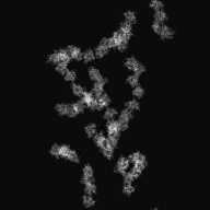
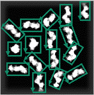
2次元画像の切り出し
傾斜画像(2D画像複数)(前処理済)

↓	切り出し範囲のSetting(Display2: 0°'s imageのみ)

0°の切り出しInformationfile(ROIInformation)

↓	各傾斜画像の切り出し範囲を計算する(現在はMakefile内で処理)

各傾斜画像の切り出しInformation

↓	画像の切り出し(mrcImageROIs)

切り出された複数's imagefile(切り出し数 × 傾斜数分)

↓	位置合わせ(mrcImageCorrelarion + Makefileの処理)

位置合わせ済みの切り出しInformation(傾斜数分)

↓	再度画像の切り出し(mrcImageROIs) (※ 切り出し画像をシフトするのではなく,切り出し位置を再Settingして切り出します)

位置合わせ済み's image(ROI)file(切り出し数 × 傾斜数分)

↓	角度InformationfileのCreate(Makefile内の処理)

角度Informationfile(切り出し数分)

↓	3次元再構成(mrc2Dto3D)

3次元画像(切り出し数分)
実行例1(1軸傾斜のサブトモグラム)
make all
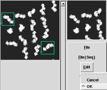
切り出し部分決めてEdit->OKで決定します. |
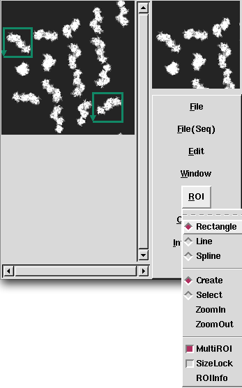
複数切り出したいときはROI->MultiROIを選択します. |
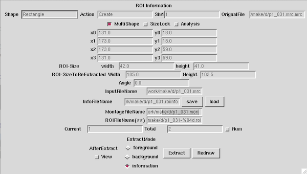
| 今回はInformationだけCreateすれば,切り出しは自動で行われます. ROI InformationウィンドウにてInfoFileName右側のsaveボタンを押すとfileがCreateされます. |
p1_031-0000.roi	Rect	20	30	60	30	60	70	20	70
p1_031-0001.roi	Rect	15	75	55	75	55	115	15	115
p1_031-0002.roi	Rect	25	110	65	110	65	150	25	150
p1_031-0003.roi	Rect	45	0	85	0	85	40	45	40
p1_031-0004.roi	Rect	60	50	100	50	100	90	60	90
p1_031-0005.roi	Rect	55	80	95	80	95	120	55	120
p1_031-0006.roi	Rect	55	120	95	120	95	160	55	160
p1_031-0007.roi	Rect	85	15	125	15	125	55	85	55
p1_031-0008.roi	Rect	85	51	125	51	125	91	85	91
p1_031-0009.roi	Rect	85	91	125	91	125	131	85	131
p1_031-0010.roi	Rect	93	130	133	130	133	170	93	170
p1_031-0011.roi	Rect	115	25	155	25	155	65	115	65
p1_031-0012.roi	Rect	120	60	160	60	160	100	120	100
p1_031-0013.roi	Rect	123	100	163	100	163	140	123	140
p1_031-0014.roi	Rect	115	140	155	140	155	180	115	180
p1_031-0015.roi	Rect	152	152	192	152	192	192	152	192
 |
||
| -60° | 0° |
60° |
| xy-plane | |
| yz-plane | |
| zx-plane |
実行例2(2軸傾斜のサブトモグラム)
| x-axis回転 | |||
| y-axis回転 |
make all
DataA_006-0000.roi Rect        0.722314      137.147614       33.000000      106.000000       49.053597      122.636041       16.775911      153.783654
DataA_006-0001.roi Rect       15.000000       79.000000       42.000000       79.000000       42.000000      107.000000       15.000000      107.000000
DataA_006-0002.roi Rect       13.000000       39.000000       58.000000       39.000000       58.000000       64.000000       13.000000       64.000000
DataA_006-0003.roi Rect       41.000000      129.000000       84.000000      129.000000       84.000000      154.000000       41.000000      154.000000
DataA_006-0004.roi Rect       51.000000       85.000000       82.000000       85.000000       82.000000      119.000000       51.000000      119.000000
DataA_006-0005.roi Rect       47.269722       69.494676       78.455043       40.316766       95.000000       58.000000       63.814679       87.177909
DataA_006-0006.roi Rect       66.000000        4.000000       92.000000        4.000000       92.000000       44.000000       66.000000       44.000000
DataA_006-0007.roi Rect       77.597890      150.922358       95.484138      132.052220      120.886248      156.129861      103.000000      175.000000
DataA_006-0008.roi Rect       93.000000       92.000000      115.000000       92.000000      115.000000      132.000000       93.000000      132.000000
DataA_006-0009.roi Rect      100.000000       51.000000      121.000000       51.000000      121.000000       93.000000      100.000000       93.000000
DataA_006-0010.roi Rect       98.589377       19.087800      119.760822       10.100593      135.000000       46.000000      113.828555       54.987208
DataA_006-0011.roi Rect      122.000000      141.000000      146.000000      141.000000      146.000000      184.000000      122.000000      184.000000
DataA_006-0012.roi Rect      136.883039       95.213292      160.000000      104.000000      144.116961      145.786708      121.000000      137.000000
DataA_006-0013.roi Rect      127.000000       73.000000      146.061183       60.635990      169.000000       96.000000      149.938817      108.364010
DataA_006-0014.roi Rect      140.000000       22.000000      177.361289       43.286947      166.470292       62.402025      129.109004       41.115078
DataA_006-0015.roi Rect      163.000000      152.000000      183.000000      152.000000      183.000000      190.000000      163.000000      190.000000
| xy-plane | |
| yz-plane | |
| zx-plane |
Interpretation of 3D Reconstruction
また,多様な構造を含むため,3次元画像から興味あるセグメントを切り出すなどの作業が必要です.そのための支援ソフトウェアが必要です.
Averaging of Subtomograms
 |
 |
 |
 |
 |
 |
 |
 |
 |
| xy-plane | yz-plane | zx-plane |
実行例1
| xy-plane | |
| yz-plane | |
| zx-plane |
Min Max |
-0.0012017 (5, 9, 13) 0.00263957 (13, 6, 15) |
| xy-plane | |
| yz-plane | |
| zx-plane |
Min Max |
-0.000536652 (6, 13, 12) 0.00177258 (13, 17, 13) |
実行例2
| xy-plane | |
| yz-plane | |
| zx-plane |
Min Max |
-5.47817 (34, 19, 20) 16.0715 (31, 22, 19) |
| xy-plane | |
| yz-plane | |
| zx-plane |
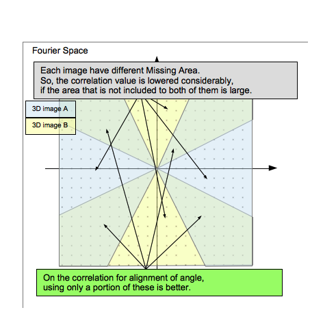
これはそれぞれのサブトモグラムの3次元像にてミッシングエリアが異なるので,どちらかにdataがない角度では相関値が大Widthに下がってしまうためです.
Min Max |
-2.32263 (22, 29, 20) 5.20816 (19, 24, 22) |


